

Written by Konstantin Dolgan, Ph.D., NPDP
Founder & CEO, Product Development Engineer
Published August 10, 2026
Turning a hand-made prototype into a production part means rebuilding it as parametric CAD, not just capturing a mesh. 3D scanning provides the reference; the manufacturable model is modeled on top of it.
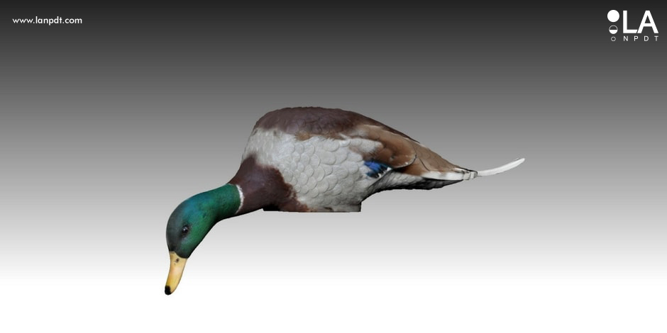
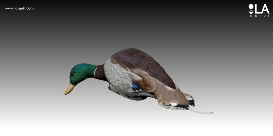
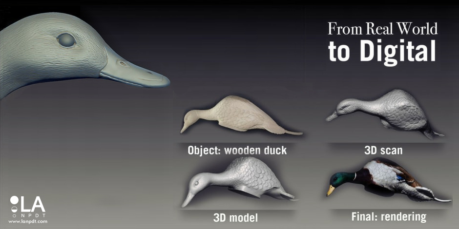
Mojo Outdoors gave us a hand-carved wooden duck decoy with an intricate feather pattern. We combined several 3D scanning and modeling techniques to recreate the detail, then produced the CAD Mojo took into manufacturing for the season.
Project at a glance
- Client
- Mojo Outdoors — motion duck decoys and hunting gear
- Category
- Outdoor and hunting products
- Starting point
- A hand-carved wooden duck prototype with intricate feather detail
- What we delivered
- 3D scanning, multi-method 3D modeling, production CAD, mold-ready parts and assembly drawings
- Key constraints
- Reproduce the carved feather pattern exactly while making the body manufacturable
- Outcome
- Mojo Outdoors moved into manufacturing in time for the duck hunting season
The client
Mojo Outdoors is a leading maker of motion duck decoys and hunting gear, known for decoys with lifelike movement that pull birds in close.
The challenge
Mojo handed us a hand-carved wooden duck prototype and needed an exact 3D model of it — every groove and line of the feather pattern intact — that a factory could actually tool.
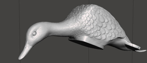
Those two goals pull against each other. A scan captures the carving but arrives as a noisy mesh with no draft, no uniform wall thickness and no parting line, and a clean moldable body tends to wash the carved detail away.
Our solution
We combined several 3D scanning and 3D modeling methods rather than relying on a single pass, using the scan data as reference and rebuilding the decoy as parametric CAD on top of it. That kept the feather texture readable while the underlying body became a form a molder could quote.
Molding rules were then applied to the model — draft angles, wall thickness, parting line and hardware interfaces around the existing motion mechanism — and dimensioned drawings were released alongside the CAD files so the factory knew which surfaces were functional and which were cosmetic.
The result
Mojo Outdoors moved the decoy into manufacturing with production-ready CAD and drawings in hand, in time for the upcoming duck hunting season, and kept an editable model it can adjust for future variants instead of re-carving and re-scanning.

Hand-carved prototypes do not become molds
Outdoor products are usually born as something built by hand in a shop — carved, welded, taped. That object carries the intent but none of the manufacturing rules: no draft, uneven walls, no place for the motor, no thought about how two halves close. Converting it is a modeling problem and a molding problem at the same time.
What we delivered for Mojo Outdoors
We captured the physical prototype, rebuilt it as parametric CAD so the client could adjust proportions later, and applied draft, uniform wall thickness, ribbing and parting lines suited to injection molding. Hardware interfaces were designed around the existing motion mechanism so assembly stayed simple on the line.
Capabilities used on this project
Rapid prototyping services
3D printing, CNC machining, urethane casting and functional prototype builds with published materials, tolerances and lead times.
Prototype design and engineering
Design for the prototype itself: CAD, tolerance stacks, material choices and assembly detail before anything is built.
From a hand-made prototype to a mold-ready part
1. Scan for reference, not for tooling
A raw scan is a mesh with noise, holes and no design intent. It is an excellent reference and a poor manufacturing model — you cannot draft, shell or split it reliably.
2. Rebuild as parametric CAD
Surfaces and features are modeled over the scan so the part can be edited later: change a wall thickness, move a boss, adjust a mating face without starting again.
3. Preserve the detail that matters
On the Mojo decoy the feather grooves are the product. We combined scanning and modeling methods specifically to keep that texture readable while the underlying body became a clean, moldable form.
4. Apply the molding rules
Draft angles, uniform wall thickness, parting line, gate and ejector locations. This is the step that turns a beautiful model into a part a molder will actually quote.
5. Release drawings with the CAD
Assembly drawings, critical dimensions and material call-outs travel with the model, so the factory knows which features are functional and which are cosmetic.
| Raw 3D scan | Production CAD | |
|---|---|---|
| Geometry | Triangle mesh | Parametric surfaces and solids |
| Editable | Barely | Fully — features and dimensions |
| Ready for molding | No | Yes, with draft and wall control |
| Best use | Reference and verification | Tooling, drawings, quoting |
Questions about this project
Straight answers from the engineers who ran the build. Have a different question? Ask us directly.
Talk to an engineerCan you 3D scan my prototype and send it straight to a factory?
Not usefully. A scan is a mesh — it has no draft, no clean parting line and no editable features. We use the scan as reference and rebuild the part as parametric CAD, which is what a molder needs to quote and cut tooling.
Will scanning capture fine surface texture?
With the right combination of methods, yes. On the Mojo decoy the feather grooves were the whole point, so we used several scanning and modeling techniques together rather than relying on a single pass.
How long does scan-to-CAD take?
For a single hand-made part, typically four to ten weeks including production CAD, DFM and drawings — driven mostly by how much detail has to be reconstructed and how many revisions the mold review triggers.
What do you need from me to start a scan-to-CAD project?
The physical part, and a description of how it is meant to be made and used. Mojo sent a hand-carved wooden prototype; anything solid enough to scan works, including a printed part or a modified off-the-shelf product.
Do I own the CAD files at the end?
Yes. You receive the native and neutral CAD plus dimensioned drawings, so you can quote the part with any manufacturer and edit it later without coming back to us.
Industries this project belongs to
See how we approach development in each of these categories, and the other products we have taken from sketch to production there.


