ADAS Sensors: Radar, Camera, LIDAR and What They Cost to Build
Which ADAS sensors deliver which features, how the stack is fused, and what hardware teams face when developing driver assistance products.
October 28, 20188 min read

Written by Konstantin Dolgan, Ph.D., NPDP
Founder & CEO, Product Development Engineer
Published October 28, 2018Updated September 2, 2026
ADAS - advanced driver assistance systems - is the layer of sensing and control that keeps a car in its lane, brakes before the driver does and warns about the vehicle in the blind spot. It is the technology bridge between fully manual driving and autonomy, and in the United States automatic emergency braking is being written into federal requirements for new light vehicles, which pulls the whole sensor stack into every trim level rather than just the luxury ones.
What is Adas?
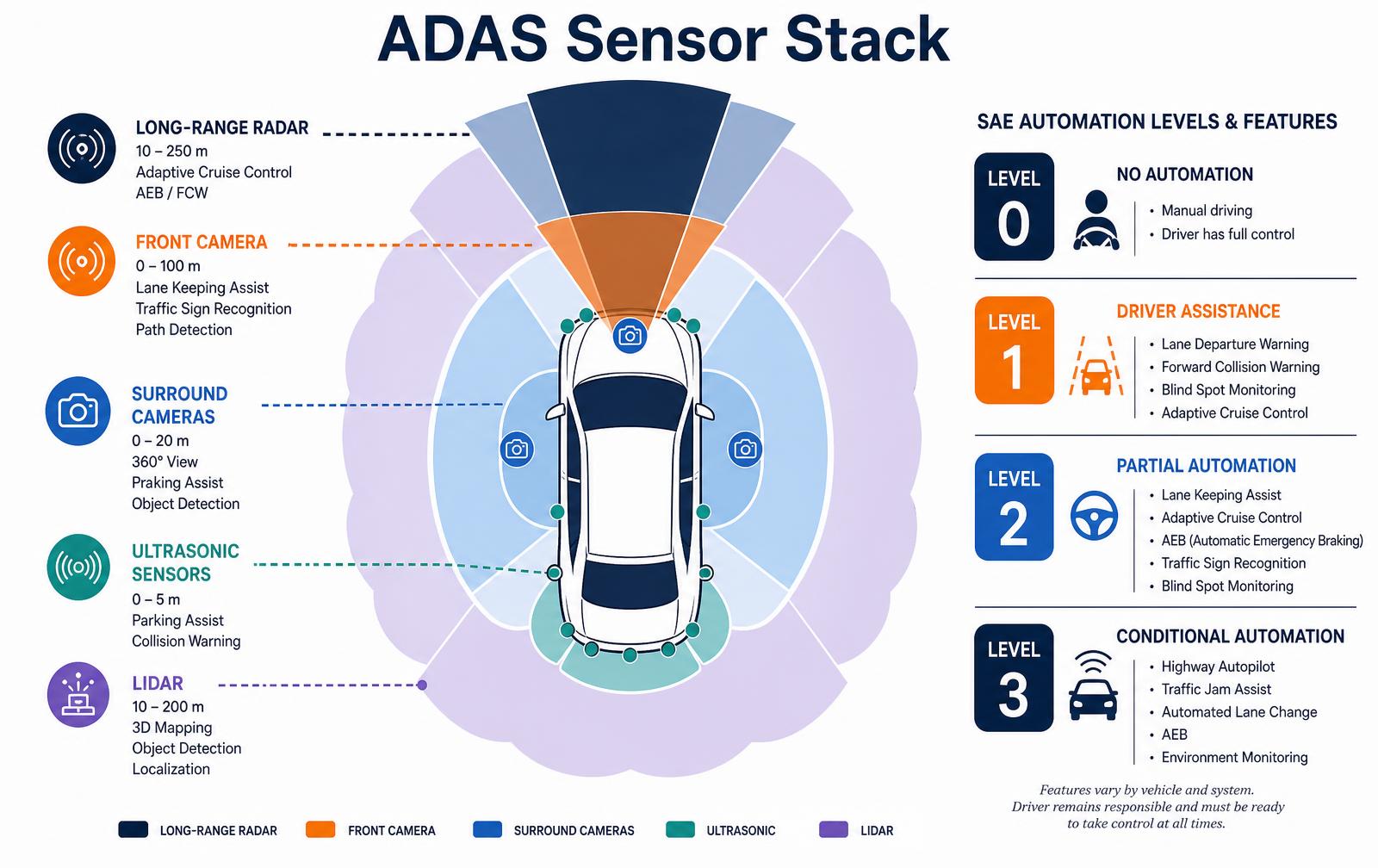
ADAS is a collection of features - not one system - built on shared perception hardware. Cameras classify what an object is. Radar measures how fast it is closing, in rain and darkness where cameras struggle.
Ultrasonic sensors handle the last five meters for parking. Lidar produces a dense 3D map for systems that need centimeter geometry. A domain controller fuses those inputs into a single model of the world and hands decisions to braking, steering and throttle actuators over the vehicle bus.
Sensor | Range | Strength | Drives these features |
|---|---|---|---|
Long-range radar | 10-250 m | Velocity, works in weather | Adaptive cruise, forward collision warning, AEB |
Corner radar | 1-80 m | Wide field, cross traffic | Blind spot, rear cross-traffic alert, lane change assist |
Front camera | 0-100 m | Classification, lane markings | Lane keeping, traffic sign recognition, pedestrian detection |
Surround cameras | 0-20 m | 360-degree context | Parking assist, surround view, door-open warning |
Ultrasonic | 0-5 m | Cheap, close range | Park assist, low-speed collision warning |
Lidar | 10-200 m | Precise 3D geometry | Conditional automation, highway pilot |
What Do the Sae Automation Levels Mean?
SAE J3016 defines six levels. Level 0 gives warnings only. Level 1 controls either speed or steering - adaptive cruise or lane centering, not both.
Level 2 combines them but the driver remains fully responsible and must monitor continuously; almost everything marketed today as a driver-assist package is Level 2.
Level 3 lets the driver disengage attention within a defined operational design domain, such as a mapped highway under a speed threshold, with a handover request. Levels 4 and 5 remove the driver inside, or beyond, that domain.
Marketing language routinely blurs 2 and 3; the legal difference is who is liable when the system errs.
Why is Adas Development So Expensive?
- Functional safety - ISO 26262 ASIL-B to ASIL-D work products, hazard analysis, redundant sensing and fail-operational power.
- SOTIF - ISO 21448 covers the hazards that occur even when nothing has failed, such as a misclassified object.
- Validation mileage - millions of simulated kilometers plus targeted track scenarios with soft-target vehicles and pedestrian mannequins.
- Calibration - every camera and radar must be aimed and calibrated at end of line, and again after a windshield replacement.
- Environmental qualification - sensors must survive thermal shock, vibration, salt spray, stone impact and EMC testing.
- Cybersecurity - ISO/SAE 21434 process obligations for anything on the vehicle bus.
How Do Suppliers Get into the Adas Supply Chain?
Most companies entering this space are not building the domain controller - they are building brackets, sensor housings, wiring, calibration fixtures, aftermarket accessories or fleet-retrofit hardware that must not interfere with existing systems.
That work still lives inside automotive discipline: IATF 16949 quality, PPAP submissions, capable tooling, and design records that survive an OEM audit. The practical entry path is a validated prototype, a documented DFMEA, and a manufacturing partner who has passed a customer-specific requirements audit before.
Phase | What happens | Duration | Budget range |
|---|---|---|---|
Concept and requirements | Use cases, ODD definition, DFMEA start | 4-8 weeks | $15k-$60k |
Engineering prototype | Mechanical, electronics, mounting and thermal | 8-16 weeks | $50k-$250k |
Validation | EMC, environmental, road and track testing | 8-20 weeks | $40k-$200k |
Production tooling and PPAP | Tools, capability studies, submission package | 12-20 weeks | $60k-$400k |
Where the technology goes next
Three trends are reshaping the stack: 4D imaging radar that resolves elevation and starts to replace low-end lidar, centralized compute that collapses a dozen ECUs into one high-performance domain controller, and over-the-air updates that let behavior improve after the car is sold.
For product teams, the practical consequence is that mechanical and electrical hardware must be specified for a software feature set that will keep changing - so thermal headroom, connector count and compute margin are design requirements, not afterthoughts.
How Adas Sensors Get Validated Before Production
Validation is where ADAS programs overrun. A sensor that performs on a sunny proving ground still has to hold calibration after thermal cycling, road salt, stone impact, and 150,000 km of vibration.
Suppliers run a fixed sequence: bench characterization, environmental stress, static target-board calibration, closed-course scenario testing, then public-road data collection measured in millions of kilometers. Each stage produces evidence that feeds the ISO 26262 safety case.
Validation stage | What it proves | Typical duration | Budget range |
|---|---|---|---|
Bench characterization | Detection range, field of view, false positive rate | 3-6 weeks | $20k-$70k |
Environmental and durability | Thermal shock, IP67 sealing, salt spray, vibration | 6-12 weeks | $35k-$120k |
EMC and radiated emissions | CISPR 25 and OEM-specific limits | 2-4 weeks | $15k-$45k |
Closed-course scenario testing | Euro NCAP style AEB and lane-keep scenarios | 4-10 weeks | $60k-$250k |
Public road data collection | Edge cases and SOTIF coverage | 3-12 months | $150k+ |
Mounting, alignment and the mechanical problems suppliers underestimate
- Bracket stiffness. A radar aimed 0.5 degrees off centre loses meaningful range at 200 m. Brackets need first natural frequency above the body structure they mount to.
- Radome design. Paint with metallic flake, ice, or a thick emblem detunes a 77 GHz radar. Radome thickness must be a multiple of half the wavelength in the material.
- Camera optical path. Windshield wedge angle, heater grid, and glass distortion all change the calibration and must be locked with the glass supplier.
- Thermal path. Perception SoCs dissipate 8-40 W in a sealed housing behind glass in direct sun; passive heat spreading has to be designed in from the start.
- Service and recalibration. Any part touched during collision repair needs a documented recalibration procedure or the fleet loses the feature after the first fender bender.
Aftermarket and Retrofit Adas
Fleet retrofit is the accessible entry point. Camera-based collision warning and driver-monitoring kits for commercial vehicles avoid the OEM sourcing cycle, sell through fleet channels, and are judged on installation time and false-alert rate rather than on ASIL decomposition.
The engineering work is still real - power management on a noisy 24 V truck bus, dashboard-safe mounting, and a data pipeline that survives cellular dropouts - but the program runs in months instead of years.
- Key takeaway 1: Budget validation as its own program phase; on ADAS it often exceeds design cost.
- Key takeaway 2: Mechanical details - bracket stiffness, radome, thermal path - decide sensor performance as much as the silicon does.
- Key takeaway 3: Recalibration after repair must be designed and documented, not discovered in the field.
- Key takeaway 4: Fleet retrofit products reach revenue years earlier than OEM sourcing.
Fusion compute and the software side of ADAS
Sensors are the visible part of an ADAS program; the compute platform and its software stack usually carry more schedule risk. Fusion needs synchronized timestamps, deterministic latency and a safety architecture that can degrade gracefully when a camera is blinded or a radar returns garbage. Choosing the compute platform early constrains everything downstream — toolchain, safety certification evidence and unit cost.
Compute platform classes
Class | Typical performance | Where it fits | Unit cost at volume |
|---|---|---|---|
Automotive MCU (lockstep) | Sub-1 TOPS | Single-sensor L1 features, safety monitor | $5-$25 |
Mid-range SoC | 5-30 TOPS | L2 camera plus radar fusion | $40-$120 |
High-end SoC | 100-500 TOPS | L2+ / L3 multi-sensor fusion | $150-$600 |
FPGA companion | Varies | Pre-processing, sensor interfaces | $30-$200 |
Software effort scales faster than hardware cost. A single-feature L1 system may take 15-30 engineer-years of software across perception, fusion, control and validation; an L2+ stack routinely exceeds 200. ISO 26262 work items — HARA, safety goals, ASIL decomposition, tool qualification — add 20-40 percent to that effort and cannot be retrofitted at the end.
Supplier readiness checklist
- Time synchronization strategy across all sensors, specified to microseconds.
- A documented degradation mode for each sensor failure, not just a fault code.
- Data logging capacity sized for the validation fleet, including storage and upload cost.
- ISO 26262 work products started at concept phase, with an ASIL allocation on paper.
- Over-the-air update path with signed images and rollback, planned before B-sample.
Key takeaways
- Compute choice locks the toolchain, safety evidence and BOM cost for the whole program.
- Software and validation, not sensors, dominate ADAS development budgets.
- Functional-safety work must start at concept; it cannot be added before SOP.
the Four Adas Sensor Types and What Each One is Bad At
Advanced driver assistance systems are built from four sensing modalities, and no single one is sufficient. Cameras read semantics — lane markings, signs, pedestrian shape — but estimate distance poorly and degrade in glare, fog and heavy rain.
Radar measures range and closing velocity directly and works through weather, but resolves shape badly and historically struggles with stationary objects. Lidar produces dense geometry with real distance accuracy but costs more and is affected by spray and reflective surfaces.
Ultrasonic sensors are cheap and precise under about five meters, which makes them parking sensors and nothing more.
Fusion exists because these weaknesses are complementary rather than overlapping. A camera classifies the object as a cyclist; radar confirms it is closing at nine meters per second; the system brakes. Remove either input and the confidence drops below the threshold where automatic intervention is safe.
Sensor | Effective range | Weather tolerance | Unit cost band | Primary weakness |
|---|---|---|---|---|
Mono camera | up to ~120 m | Poor in fog, glare, heavy rain | $15–$60 | Distance estimation |
Stereo camera | up to ~60 m | Poor in low light | $60–$200 | Calibration drift |
Short-range radar | 0.5–40 m | Excellent | $25–$80 | Low angular resolution |
Long-range radar | 10–250 m | Excellent | $80–$250 | Narrow field of view |
Lidar | up to ~200 m | Moderate — spray degrades returns | $300–$1,200 | Cost and packaging volume |
Ultrasonic | 0.2–5 m | Good | $3–$10 | Useless above parking speed |
What this means outside the automotive OEM world
Most teams we work with are not building cars. They are building aftermarket safety products, fleet retrofit units, work-zone equipment, e-bike and scooter systems, or industrial vehicles operating in mixed pedestrian traffic. The engineering problem is the same sensing physics with a fraction of the budget and none of the OEM validation infrastructure, so scope discipline decides whether the product ships.
The reliable pattern is to pick one hazard, solve it completely and claim only that. A blind-spot alert that works at every speed and in rain is a product; a general collision-avoidance claim on a single camera is a liability. Mounting is the second overlooked constraint: sensor position determines field of view, and retrofit brackets have to survive vibration, thermal cycling and pressure washing.
- Define one hazard and one intervention; resist the temptation to claim general collision avoidance
- Specify the operating envelope explicitly — speed range, lighting, weather, mounting height
- Budget for calibration: every camera-based system needs a repeatable field calibration procedure
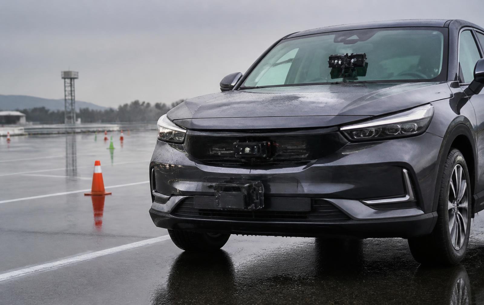
- Validate on wet asphalt, at dusk and against low-contrast targets, not only in a clean parking lot
- Design the enclosure for IP67 minimum, thermal cycling and pressure washing if fleet-mounted
- Log raw sensor data during pilot deployments; you cannot debug a false alert from a user report alone
- Have counsel review every safety claim before it appears on packaging or in a spec sheet
Frequently asked questions
Can I build a credible ADAS product with a camera alone? For alerting, sometimes. For automatic intervention, no. Camera-only systems cannot reliably measure closing speed, and intervention without that measurement produces false braking, which is its own hazard.
How much does radar add to a bill of materials? A short-range automotive-grade radar module lands between twenty-five and eighty dollars at moderate volume, plus the antenna keep-out volume and a radar-transparent enclosure window, which often costs more in packaging than the module costs in parts.
What certification applies to aftermarket safety devices? It depends on the market and the claim. Radio modules need FCC or CE radio approval; anything mounted in the driver's field of view faces visibility regulation; fleet buyers usually impose their own vibration and ingress standards on top. Identify the applicable set before enclosure design, not after.
How long does a fleet-grade sensor product take to develop? Typically twelve to twenty months from concept to production with a validation season built in, because you must test across weather conditions that only occur at certain times of year. Comparable programs, including electronics development and enclosure work, are documented in our portfolio, and scoping usually starts with a consulting engagement.
We take vehicle-adjacent products from requirements through validated prototypes and production-ready documentation.
Work with LA NPDT: if you are moving from here to execution, start with our product development consulting or talk to us about end-to-end product development.
Filed under:Tech
Services related to this guide
- Product design servicesIndustrial design and CAD taken all the way to manufacturable files.
- Rapid prototypingWorking prototypes in days, from 3D printing to vacuum casting.
- Electronic design servicesSchematic, PCB layout, firmware and bring-up, through to production handoff.
- Product development examplesReal projects we designed, prototyped and shipped.