Bendable Electronics: Flex, Rigid-Flex and Stretchable Circuits
Bendable electronics are no longer a lab curiosity. Here is what flex, rigid-flex and stretchable circuits cost, where they fail, and how to choose between them.
November 20, 20198 min read

Written by Konstantin Dolgan, Ph.D., NPDP
Founder & CEO, Product Development Engineer
Published November 20, 2019Updated September 2, 2026
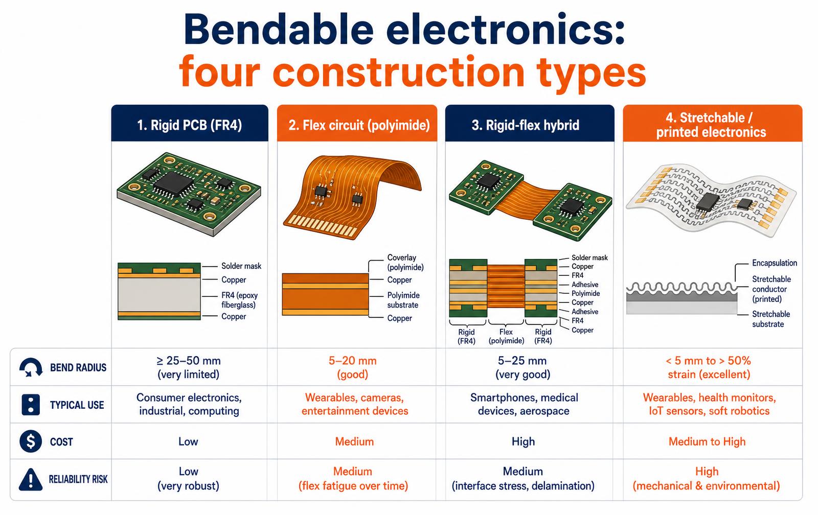
Bendable electronics are circuits built on a flexible substrate — usually polyimide instead of rigid fiberglass — so the board can fold, curve or flex as part of the product rather than sitting flat inside a box. They exist in four practical forms: rigid boards, flex circuits, rigid-flex hybrids and stretchable printed electronics.
Choosing among them is a mechanical decision as much as an electrical one, and it is made early, because it changes enclosure design, assembly and cost.
Why bendable at all
Flexible construction is rarely chosen because bending looks impressive. It is chosen because it removes connectors and wire harnesses, fits electronics into a curved or very thin housing, survives repeated motion in a hinge or wearable, and cuts assembly labor by replacing several parts with one folded circuit.
Every one of those is a reliability and cost argument, which is why flex shows up in phones, cameras, hearing aids, medical wearables and automotive interiors long before it shows up in a marketing headline.
The four constructions
Construction | What it is | Best for | Watch out for |
|---|---|---|---|
Rigid PCB | Copper on FR4 epoxy glass | Anything that can stay flat | Needs cables and connectors to reach anywhere else |
Flex circuit | Copper on thin polyimide film with coverlay | Curved surfaces, hinges, thin devices, harness replacement | Flex fatigue at tight bends, panel and tooling cost |
Rigid-flex | Rigid sections joined by integrated flex layers | Dense electronics in a folded assembly, medical and aerospace | Highest board cost, longer fabrication lead time |
Stretchable / printed | Serpentine or printed conductors on elastomer | Skin-contact wearables, soft robotics, sensor patches | Immature supply base, environmental and strain reliability |
Two more distinctions matter in a quote. A flex-to-install circuit is bent once during assembly and then stays put; a dynamic flex circuit bends thousands or millions of times in service. They are different designs — different copper, different bend radius, different stack-up — and confusing the two is the single most common cause of field failures in bendable electronics.
Design rules that decide whether it survives
- Respect the bend radius. A common starting point is roughly ten times the flex thickness for a static bend and far more for dynamic flexing. Tighter bends buy you packaging space and cost you cycles.
- Use rolled annealed copper for dynamic bends. Its grain structure tolerates repeated flexing much better than standard electrodeposited copper.
- Keep the traces in the neutral axis and route them perpendicular to the bend. Traces that turn inside a bend zone concentrate strain and crack.
- Never place components, vias or stiffener edges in a bend zone. The transition from stiff to flexible is where the circuit tears.
- Curve, do not corner. Rounded trace corners and teardrop pads spread stress; sharp geometry concentrates it.
- Add stiffeners under connectors and BGA areas so mating forces are not carried by the film.
What it costs, and when it pays back
Per square inch, a flex circuit costs more than a rigid board and rigid-flex costs more again. The comparison that matters is not board versus board but assembly versus assembly.
When a flex circuit deletes two connectors, a wire harness, a labor step and a common field failure, it frequently wins on total cost even though the bare board line item went up. Ask your contract manufacturer to quote both architectures at your target volume before deciding — the crossover point is product-specific.
How to test a bendable design
- Build a paper or film mock-up of the flex first. Fold it into the real enclosure before the layout is final; most flex geometry errors are visible on paper.
- Cycle test to the product's real duty. If a hinge opens twenty times a day for five years, that is tens of thousands of cycles, plus a margin.
- Test at temperature and humidity extremes, since adhesive and copper behave differently when hot, cold or damp.
- Run EMC pre-compliance early. Folded circuits change ground return paths and radiate differently than the flat version you simulated.
Choosing between flex, rigid-flex and stretchable
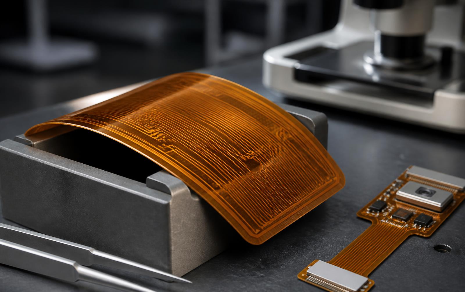
The three technologies solve different problems. A single-sided flex circuit is a cable replacement: it removes connectors, saves space and takes a fixed bend. Rigid-flex fuses rigid board sections to flex layers so an assembly can fold into a housing with no interconnects at all. Stretchable circuits, built on elastomer with serpentine conductors, exist for skin-worn and soft-robotics applications where the substrate has to deform, not just bend.
Cost climbs steeply across that list, and so does the number of vendors capable of building it well.

Technology | Bend behaviour | Typical layer count | Relative cost | Common use |
|---|---|---|---|---|
Single/double-sided flex | Static or gentle dynamic | 1 - 2 | 1x | Cable replacement, hinges |
Multilayer flex | Static bend | 3 - 8 | 2 - 3x | Dense wearables |
Rigid-flex | Fold to install | 4 - 20 | 4 - 8x | Cameras, medical, aerospace |
Stretchable | Deforms 10 - 100% | 1 - 3 | 10x+ | Skin patches, soft robotics |
Design rules that prevent field cracking
- Bend radius. Keep static bends above roughly 6x material thickness and dynamic bends above 100x; dynamic flex wants single-sided copper on the neutral axis.
- Rolled annealed copper for anything that moves. Electrodeposited copper is cheaper and fails far sooner in flexure.
- No plated through-holes in the bend zone. Vias in a flexing area are the classic failure signature.
- Stagger traces on opposite layers rather than stacking them, and route them perpendicular to the bend line.
- Add teardrops and strain relief at the rigid-to-flex transition, and keep components clear of that boundary.
Key takeaways
- Flex replaces cables, rigid-flex replaces connectors, stretchable replaces the assumption of a rigid substrate.
- Dynamic bending needs rolled annealed copper, single-sided routing and a generous radius.
- Cost rises roughly an order of magnitude from simple flex to stretchable, and vendor choice narrows with it.
- Involve the fabricator during layout; flex stackups are far less forgiving than rigid boards.
Frequently asked questions
What are bendable electronics used for?
Phones and foldables, cameras, hearing aids and other tiny consumer devices, medical wearables and disposable sensor patches, automotive displays and interior controls, and industrial equipment where a circuit must follow a curved surface or move with a hinge.
Is a flex circuit less reliable than a rigid PCB?
Not inherently. A correctly designed flex circuit often improves reliability by eliminating connectors and solder joints, which are the usual failure points. Flex fails when it is bent tighter than its design allows, flexed dynamically with the wrong copper, or stressed at a stiffener transition.
How much more does rigid-flex cost than a rigid board?
Bare-board cost is typically several times higher, and the gap narrows with volume. Judge it at the assembly level: rigid-flex removes connectors, cables, assembly labor and test steps, so the finished-device cost difference is much smaller than the board quotes suggest, and sometimes negative.
Can you prototype flex circuits in small quantities?
Yes. Several fabricators offer low-quantity flex and rigid-flex prototypes with lead times measured in one to three weeks. Budget for at least two spins: the first one usually teaches you something about how the circuit actually folds inside the enclosure.
Connectors and assembly: where flex designs actually fail
Most flex circuit failures happen at the interface, not in the middle of the bend. Terminations concentrate stress, and assembly processes designed for rigid boards handle thin polyimide badly. Choosing the termination method early changes stack-up, stiffener placement and even the panel layout your fabricator can offer.
Termination methods compared
Method | Best for | Rework | Watch out for |
|---|---|---|---|
ZIF connector on stiffened tail | Serviceable assemblies | Easy | Tail thickness must match connector spec |
ACF hot-bar bonding | Fine pitch, displays | None | Needs process development and tooling |
Direct solder to rigid board | Low cost, low volume | Difficult | Strain relief required at the joint |
Rigid-flex integrated | Highest reliability | N/A | Higher fabrication cost and longer lead time |
Crimp or pigtail wiring | Prototypes, low pin count | Easy | Bulk and hand-build variability |
Add a stiffener under every connector and every component pad, keep traces out of the transition zone between stiffened and unstiffened areas, and never route a bend across a plated through-hole. These three rules eliminate the majority of field cracking reported on first-generation flex designs.
Sourcing and prototype checklist
- Send the fabricator your bend radius and cycle count, not just the Gerbers.
- Confirm coverlay versus solder-mask choice with the assembler before layout.
- Order a bare-board flex sample and fold it by hand before committing to assembly.
- Specify polyimide thickness and copper type (RA versus ED) explicitly — RA copper for dynamic bends.
- Ask for the fabricator's panel utilization; it drives unit price more than layer count at low volume.
Key takeaways
- Terminations, not bends, cause most flex circuit failures.
- Pick the connector strategy before layout; it shapes the whole stack-up.
- Rolled-annealed copper and correct stiffener placement decide dynamic bend life.
Materials and stack-up: the choices you cannot change later
Two decisions made in the first week of layout determine whether a bendable circuit survives: the substrate and adhesive system, and where the copper sits in the stack.
Polyimide is the default film because it tolerates soldering temperatures and repeated flexure; PET is cheaper and used for single-use printed sensors that never see a reflow oven. Adhesiveless laminates cost more but flex better, because there is no soft adhesive layer to shear at the bend.
Layer choice | Typical spec | Effect on bend life | Cost impact |
|---|---|---|---|
Substrate film | Polyimide 1 - 2 mil | Thinner film bends tighter | Neutral |
Copper type | Rolled annealed, 0.5 - 1 oz | RA copper survives 10x more cycles than ED | Slight increase |
Laminate | Adhesiveless vs adhesive-based | Adhesiveless reduces delamination and shear | 10 - 20% increase |
Coverlay | Polyimide coverlay vs flexible solder mask | Coverlay is the only real choice for dynamic bends | Small increase |
Stiffener | FR4 or polyimide under connectors | Prevents tearing at terminations | Low |
Qualification testing that predicts field life
- Dynamic flex cycling at the design radius to at least twice the expected lifetime cycle count, with continuous resistance monitoring rather than a pass or fail check at the end.
- Thermal cycling across the product operating range, because copper, adhesive and film expand at different rates and the bend zone accumulates the difference.
- Damp heat exposure for anything worn on the body or used outdoors; moisture ingress at the coverlay edge is a slow failure that never shows up in a short test.
- Peel and pull testing at every termination, since connectors and solder joints carry the assembly loads.
- In-enclosure fold verification with production-intent parts, because the bend the circuit actually sees is set by the housing, not the drawing.
Record the failure mode, not just the cycle count. A crack in the middle of a bend means the radius or copper choice is wrong. A crack at a stiffener edge means the transition needs relief. An intermittent open at a connector means the assembly process, not the circuit, is the problem. Those three signatures lead to entirely different fixes, and teams routinely respin the wrong thing.
Cost drivers at prototype and production volume
Driver | Prototype effect | Production effect |
|---|---|---|
Panel utilization | Minor | Dominant - odd outlines waste 30%+ of a panel |
Layer count | Moderate | Moderate, compounding with yield |
Stiffener and coverlay openings | Adds setup | Adds a labor step per unit |
Controlled impedance | Adds test coupons | Adds test time and scrap |
Assembly fixturing | One-off carrier cost | Amortized, but required for repeatability |
Ask the fabricator to nest your outline on their standard panel before the mechanical outline is frozen. A five millimetre change to a tail length can improve panel yield by a full row of parts, which at production volume outweighs almost every other saving available in the design.
Choosing a flex fabricator and assembler
Flex and rigid-flex are not commodity purchases. A shop that produces excellent rigid boards may subcontract the flex work, which means the engineering support you need during layout is one company removed from the people building your part. Ask directly whether the flex layers are fabricated in house, how many rigid-flex jobs the shop runs a month, and whether they will review your stack-up before you release.
The assembler matters just as much. Thin polyimide needs dedicated carriers through reflow, hand-loading a flex panel warps it, and pick-and-place programs written for rigid boards will not hold position on an unsupported film.
Confirm that the assembler has run flex before and ask to see the carrier design they intend to use. Prototype builds hide these problems because they are hand-assembled with unlimited care; the first production run is where an unqualified process reveals itself as a yield number.
Finally, treat the two vendors as one decision. The fabricator sets the stiffener and coverlay geometry, and the assembler depends on it for fixturing. When they are chosen independently and never speak, the gap between them becomes your rework cost.
Working on something like this?
LA NPDT takes products from concept through engineering, prototyping and production. Tell us where your project stands and we will tell you what it takes.
From the archive
Work with LA NPDT: if you are moving from here to execution, start with our CAD engineering services or talk to us about design optimization.
Filed under:Tech Talk Podcast
Tagged:ElectronicsHaptic TechnologiesLatest DevicesLatest GadgetsMicrosoftNew GadgetsNew MaterialsNew ProductsScience UpdatesTechnology Updates
Services related to this guide
- Product design servicesIndustrial design and CAD taken all the way to manufacturable files.
- Rapid prototypingWorking prototypes in days, from 3D printing to vacuum casting.
- Electronic design servicesSchematic, PCB layout, firmware and bring-up, through to production handoff.
- Product development examplesReal projects we designed, prototyped and shipped.