Design for Manufacture: Principles, Checklist and Real Savings
DFM is where unit cost is actually decided. Here are the principles, a ten-point checklist, process rules and what a proper DFM review saves.
October 10, 20186 min read

Written by Konstantin Dolgan, Ph.D., NPDP
Founder & CEO, Product Development Engineer
Published October 10, 2018Updated September 2, 2026
Design for manufacture (DFM) is the practice of designing a part so the chosen production process can make it repeatably, at the target cost. Roughly 70% of a product unit cost is locked by the time the design is frozen, so DFM is not a cost-reduction exercise you run later - it is a design input you apply from the first concept review.
The core principles
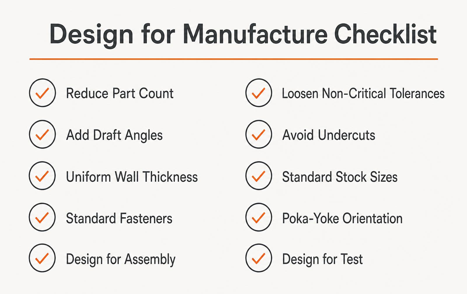
- Reduce part count. Every part removed removes a tool, a supplier, an inspection and an assembly step.
- Design for the process. A molded part and a machined part are different designs, not the same design in a different material.
- Loosen every tolerance that does not matter. Tight tolerance on a non-functional surface is pure cost.
- Standardize. Standard fasteners, stock sizes and common materials beat custom every time.
- Make assembly foolproof. If a part can be installed backwards, it eventually will be.
- Design for test. Test points and access matter as much as fit and finish.
Process-specific rules that cost the most when broken
Process | Rule | What it costs to ignore |
|---|---|---|
Injection molding | Uniform wall thickness, 1-3 degrees draft | Sink marks, warp, ejection damage, tool rework |
Injection molding | Avoid undercuts unless justified | Side actions add $3,000-$20,000 per tool |
CNC machining | Internal corner radii larger than the tool | Slower cuts or an impossible feature |
CNC machining | Limit deep, narrow pockets | Long tools, chatter, 2-3x cycle time |
Sheet metal | Bend radius at least material thickness | Cracking and inconsistent flanges |
PCBA | Respect fabricator minimum trace and space | Yield loss and higher board price |
Assembly | Design one-direction insertion | Line errors, rework, warranty returns |
What a DFM review actually returns
Change | Typical effect | Typical annual saving at 25k units |
|---|---|---|
Combine two molded parts into one | One less tool and assembly step | $25,000-$70,000 |
Remove a side action | Simpler tool, faster cycle | $15,000-$45,000 |
Swap custom fastener for standard | Lower part price and no MOQ risk | $5,000-$20,000 |
Loosen non-critical tolerances | Higher yield, cheaper process | $10,000-$40,000 |
Reduce wall thickness 20% | Less material, shorter cycle | $12,000-$35,000 |
A structured DFM review on a moderately complex product costs $8,000-$30,000 and typically returns several times that in the first production year, before counting avoided tool changes. Tool modifications after steel is cut run $2,000-$25,000 each and cost two to six weeks of schedule.
When to run DFM
- Concept review - choose the process before the geometry hardens.
- Detailed design - run part-level DFM every two weeks, not once at the end.
- Pre-tooling - full review with the actual molder or machinist, not a generic checklist.
- Post-pilot - use yield and scrap data from the pilot run to close the loop.
- Never after tooling. At that point DFM findings become change orders.
DFM and DFA are not the same thing
DFM optimizes how each part is made. Design for assembly (DFA) optimizes how parts go together - fewer fasteners, self-locating features, one insertion direction, no fixtures. DFA usually finds bigger savings on labor-heavy products, and the two run together in a proper review. Our engineering team runs both against supplier feedback rather than in isolation.
Frequently asked questions
What is design for manufacture?
Design for manufacture is the practice of shaping a design around the constraints and economics of the production process that will make it, so parts can be produced repeatably at the target cost and quality.
What is the difference between DFM and DFA?
DFM focuses on making each individual part economically - wall thickness, draft, tolerances, process fit. DFA focuses on putting parts together - part count, fasteners, insertion direction and handling. Together they are often written as DFMA.
When should DFM start?
At concept, when the production process is selected. Applying DFM after design freeze converts findings into tooling changes that cost $2,000-$25,000 each and add weeks to the schedule.
How much does a DFM review cost?
A focused review on a small assembly runs $3,000-$8,000. A full review on a moderately complex product with tooling recommendations typically costs $8,000-$30,000 and pays for itself in the first production year.
We review your CAD against the real process and supplier, then hand you a prioritized change list with the cost impact of each item.
Cost is committed long before it is spent
Design for manufacture is the practice of shaping a design around the realities of the process that will make it.
It matters because of a timing asymmetry every hardware team eventually learns the hard way: roughly 70-80% of a product's eventual unit cost is locked in during design, while nearly all of the spending happens later.
By the time a quote arrives, the expensive decisions have already been made — wall thicknesses, tolerances, part count, material choices and assembly sequence.
The useful mental model is that every design decision writes a cheque the manufacturing process cashes at volume. A tolerance tightened out of caution costs pennies once and thousands across a production year.
Universal rules, whatever the process
- Reduce part count: every part carries a purchase order, an inspection, a place in the assembly sequence and a chance to be wrong.
- Design for one orientation of assembly, and make parts either symmetric enough to be inserted any way or asymmetric enough that the wrong way is impossible.
- Standardise fasteners to the shortest practical list — one driver on the line beats a perfectly optimised mix.
- Prefer self-locating features over fixtures and jigs; a boss and slot cost nothing per unit, a fixture costs setup and drift.
- Specify tight tolerances only where the function requires them, and state which surface is the datum.
- Design test access in — pads, ports and probe points added late become secondary operations.
Process-specific rules that pay immediately
Process | Cost drivers | Rules that pay | Typical tolerance |
|---|---|---|---|
Injection moulding | Tool complexity, cycle time, cavitation | Uniform walls, 1-2° draft, ribs at 50-60% of wall, no undercuts unless justified | ±0.1-0.25 mm |
CNC machining | Setups, tool reach, material removal | Fewer setups, standard tool radii, avoid deep narrow pockets | ±0.025-0.125 mm |
Sheet metal | Bends, tooling hits, nesting | Bend radius ≥ material thickness, relief cuts, consistent hole-to-edge distance | ±0.25 mm |
Die casting | Tool life, porosity control | Uniform sections, generous fillets, plan machining allowance | ±0.1-0.4 mm |
PCB assembly | Part count, unique parts, test time | Single-sided placement where possible, consolidated BOM, fiducials and test pads | Per IPC class |
3D printing (production) | Build time, support removal | Self-supporting angles, avoid support in functional surfaces | ±0.2-0.5 mm |
Tolerance discipline
Tolerance is where good engineers spend money without noticing. The cost curve is not linear: halving a tolerance can double a feature's cost, because it moves the part from a standard process capability into inspection, secondary operations and scrap. Tolerance stack-up analysis is the corrective — model the assembly, find the small number of dimensions that actually control fit, and loosen everything else.
Approach | When to use | Effect on cost |
|---|---|---|
Default shop tolerance | Non-functional features, cosmetic surfaces | Baseline |
Worst-case stack-up | Safety-critical fits, small quantities | Conservative, drives tight individual tolerances |
Statistical (RSS) stack-up | Volume production with process data | Permits looser individual tolerances at same assembly yield |
GD&T with clear datums | Any part with an assembly relationship | Reduces argument, reduces false rejects |
Run the DFM review before the design is finished
A DFM review after design release is a change-order generator. Run the first one when the concept is chosen and the geometry is still soft, and a second before tooling release. Bring the manufacturer into the first one — the shop that will make the part knows its own constraints better than any generic guideline.
- Is every part necessary, or can two be combined or one eliminated?
- Can each part be made in the intended process without secondary operations?
- Are all tolerances justified by a function, with datums specified?
- Does the assembly proceed in one direction, without reorientation or blind alignment?
- Are materials commonly stocked in the region where the part will be made?
- Have long-lead and single-source components been identified with an alternate?
- Is inspection defined — what is measured, how, and against which acceptance limit?
- Has the manufacturer reviewed the model and returned a written DFM report?
What DFM does not mean
Design for manufacture is not a licence to strip capability. The goal is to remove cost that the customer never perceives — a tolerance nobody needs, a part that exists because two teams drew the same boundary differently, a finish specified out of habit. When a DFM suggestion removes something a user will notice, it stops being DFM and becomes a product decision, and it belongs with the people who own the product's positioning.
From idea to a part a factory can make
New technology becomes a product at the moment someone decides how it will be made. That decision, design for manufacture, is where most of the eventual unit cost is locked in — long before purchasing negotiates a price. Wall thickness, draft, tolerance stack, fastener count, and the number of unique parts each carry a cost that compounds across every unit produced.
The practical discipline is to run a manufacturability review at the end of every design phase rather than once at the end. Early reviews can still change architecture, which is where the large savings live. Late reviews can only change radii and finishes, which is why late DFM feels like nitpicking: by then the expensive decisions have already been made.
- Reduce unique part count before optimising any single part.
- Set tolerances from function, not habit; every extra decimal place buys a more expensive process.
- Design in draft and uniform wall thickness from the first solid model, not after the mold quote.
- Choose fasteners and joining methods with assembly time in mind — snap fits pay back at volume.
- Review with the actual supplier who will make the part, before design freeze.
Work with LA NPDT: if you are moving from here to execution, start with our low-volume manufacturing or talk to us about design for manufacturing.
Frequently asked questions
What is design for manufacture?
Design for manufacture is the practice of designing parts and assemblies so they can be produced reliably and economically by a specific process — adjusting geometry, tolerances, materials and part count to match how the product will actually be made.
When should a DFM review happen?
Twice at minimum: once at concept selection while geometry is still easy to change, and once before tooling release. Involve the intended manufacturer in both.
How much can DFM save?
Typical savings on a first-generation product range from 15% to 40% of unit cost, most of it from part count reduction, tolerance rationalisation and choosing a process that suits the geometry.
Does DFM apply to low-volume products?
Yes, but the levers change. At low volume, setup count and material availability dominate, so fewer machining setups and stocked materials matter more than cycle time or cavitation.
Filed under:Education
Tagged:MarketingOnline ReviewsProduct DevelopmentProduct Marketing
Services related to this guide
- Product design servicesIndustrial design and CAD taken all the way to manufacturable files.
- Rapid prototypingWorking prototypes in days, from 3D printing to vacuum casting.
- Electronic design servicesSchematic, PCB layout, firmware and bring-up, through to production handoff.
- Product development examplesReal projects we designed, prototyped and shipped.