Can your AI generated product actually be built?
An AI generated product design looks finished but rarely is manufacturable. Here is what changes when a render meets tooling, tolerances and real factory cost.
July 1, 20269 min read

Written by Konstantin Dolgan, Ph.D., NPDP
Founder & CEO, Product Development Engineer
Published July 1, 2026Updated October 8, 2026
← Back to blog LA NPDT / Editorial
In this piece
Start here
Talk to a human
Not sure where to begin? Tell us what you are building and a senior engineer will reply within one business day.
Explore more
Browse all articles on AI product development, manufacturability, and design for manufacturing.
Blog · Manufacturability · 9 min
Short answer: usually yes, but almost never as drawn. Here is what real product manufacturability looks like when an AI render meets a real factory, in blocks you can skim in two minutes.
The honest answer
An ai generated product render is a hypothesis about form. Manufacturing is a constraint on that hypothesis. The part that actually ships is the manufacturable rewrite of the render.
What changes at LA NPDT
One senior team owns industrial design, engineering, prototyping, design for manufacturing, tooling, and pilot production. No handoffs, no requote tax.
Accountable team
Concept to pilot production
3–6
Weeks to prototype
First manufacturable functional build in hand
Vendor handoffs
Same team carries the part all the way to tooling.
The pattern is consistent across every ai generated product we have reviewed in the last 18 months. A founder arrives with a clean, well lit render: a confident product silhouette, plausible materials, a friendly color story.
It is good enough to raise money on, good enough to put on a deck, good enough to convince an investor that the work is half done. The render is a beautiful answer to a different question. It answers what should this look like.
It does not answer how does this part come out of a tool, how does the cable route past the battery, how does a worker on a line assemble 1,200 of these per shift without losing a fingernail.
So our first job is rarely to draw. It is to read. We mark up the render in three colors: load bearing geometry that has to survive, cosmetic geometry we are free to evolve, and AI invented geometry that simply does not exist in the physical world. That single pass tends to recover 60 to 70 percent of the original visual intent inside a manufacturable envelope, and it is the cheapest hour of engineering anyone will ever buy.
7 things AI image models get wrong about manufacturability
Wall thickness. Invented for looks, splits or sinks on a real molded part.
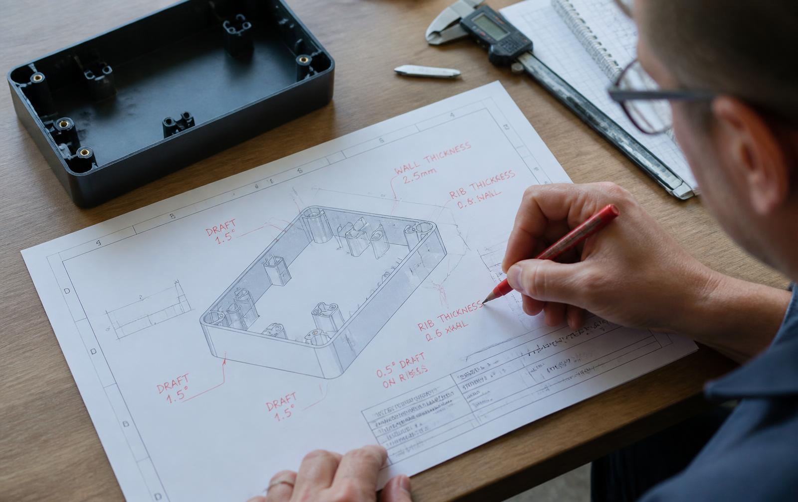
Draft angles. Vertical walls do not eject. Real parts need taper.
Undercuts. Hidden geometry that forces side actions and doubles tool cost.
Material. The finish in the render does not exist in the price band.
Tolerances. Invented numbers. The function dictates the tolerance budget.
Assembly. Snap fits with no engagement, fasteners with no access, glue joints with no surface.
07 / The expensive one
Supplier reality. The AI suggests parts (motors, sensors, batteries, connectors) that are not stocked at volume in your market. A senior engineer cross checks every BOM line in the first DFM pass.
Building the AI render literally is usually the most expensive way to fail. Engineering the strongest version of what the render was trying to say is the cheapest way to ship. LA NPDT team
What real DFM analysis actually checks
A useful dfm analysis on an AI generated product is not a polish phase. It is the lens we use from the first sketch. Wall thickness, parting lines, draft, ejector access, gate location, secondary operations, assembly sequence, service access, end of life. Every one of those questions is cheap to answer while the geometry is still in CAD. Every one of them is expensive after a tool is cut.
Doing this early is what makes the prototype useful. A prototype shaped by DFM thinking maps cleanly onto the production part. A prototype designed only to look like the render does not. See also our product discovery and industrial design pages for how the same team carries this through.
For broader engineering reference, the NIST Baldrige performance framework covers operational discipline and the NASA Systems Engineering Handbook is the canonical reference on integrated engineering across stages.
Wall thickness invented by an AI render almost always shows up as a sink mark on the first molded part. Catching it in CAD costs an hour. Catching it in steel costs a tool revision.
The reason DFM has to live at the front of the project is economic, not stylistic. The cost curve of a product is set in the first three weeks of CAD and locked when a tool is cut. After tooling, every change is a steel revision, a requalification, and a delay measured in weeks.
The literature is unambiguous on this: research from the manufacturing engineering community has long held that 70 to 80 percent of a product's lifecycle cost is committed during early design. We treat that number as a budget. Every decision in the first DFM pass is a deliberate spend against it.
What this looks like in practice is unglamorous. We do not start with a beauty render of the manufacturable version.
We start with a parting line diagram, a draft analysis colored on the CAD, a list of every undercut and what it costs in tool actions, and a one page material short list with hard numbers for cost, finish, and lead time. That document is usually four to six pages.
It is the document that decides whether the project ships at a healthy margin or limps to break even.
The prototype to production arc, as one continuous path
Stage 1. Read the render
Mark up structurally load bearing geometry vs cosmetic vs AI invented. Write the real brief.
Stage 2. Manufacturable CAD
Rewrite the geometry for the production process (mold, machined, sheet, printed) with the original vision intact.
Stage 3. Functional prototype
Real materials in the parts that matter. Prove the riskiest assumption first.
Stage 4. Pilot run
Short run manufacturing on production intent tooling. Treat prototype to production as one continuous arc, not two projects.
The first functional prototype is the moment the AI render stops being a hypothesis. Snap fits either click or they do not, regardless of how the render shaded them.
What surprises most first time hardware founders is how quickly the prototype phase compresses uncertainty. A render can be argued with for months. A printed part on a workbench cannot.
Within 20 minutes of holding the first functional build, the team and the founder are usually aligned on the next three design moves, because the part is doing the talking.
That is the real value of putting prototyping inside the same team that drew the CAD: the loop between learning and redesigning is hours, not weeks. There is no requote, no PO, no kickoff call. The same engineer who watched the snap fit fail walks back to the workstation and fixes it.
From there, the path to short run manufacturing stops looking like a separate project. The CAD that produced the prototype is the same CAD that produces the pilot tool. The materials are the same materials.
The supplier is on the same call. This is what we mean when we say prototype to production should be one arc. The agency model breaks the arc, charges separately for each segment, and forces the founder to translate every decision twice. The LA NPDT model keeps it intact.
Two parallel questions: can it be built, and should it be built this way?
Yes is rarely the whole answer. A manufacturable rewrite of an AI render is almost always possible. The better questions are: at what unit cost, at what tooling investment, against what regulation (FCC, CE, RoHS, UL, FDA), and with what serviceable lifecycle. Those answers come out of the same DFM pass, not a separate market study, because the geometry decisions drive the cost.
That is why running this work with one accountable senior team beats the agency model. The engineer who flags the cost risk on Monday is the same engineer redesigning around it on Friday. No restart of the learning curve. No vision lost in translation between vendors.
Send us the AI render. We will tell you if it can be built, this week.
Mutual NDA first. Senior engineer replies with a real manufacturability read and a one page Concept to Build Plan within the week.
Frequently asked
Can an AI generated product actually be manufactured?
Sometimes yes, often not as drawn. The render is a hypothesis about form. Real product manufacturability depends on geometry the AI did not check: wall thickness, draft, parting lines, tolerance budget, material, supplier, and assembly. A senior engineer rewrites the manufacturable version of the render in the first week, with the original vision intact.
How do you test manufacturability before paying for tooling?
A focused DFM analysis on the CAD, plus a functional prototype that proves the riskiest geometry. The point of design for manufacturing this early is to fail cheaply on a print bed, not in steel. We run that pass before any tool is quoted.
What kills most AI generated products at the manufacturing stage?
Three things. Wall thickness the AI invented for looks (cracks, sinks, warpage). Materials that cannot hit the finish or function at price. Assembly the AI ignored entirely (snap fits that do not snap, fasteners with no access). All three are visible in the first 30 minutes of a real DFM review.
How long from AI render to a manufacturable prototype?
Typically 3 to 6 weeks from a locked build direction. Because the same LA NPDT team owns CAD, prototyping, DFM, tooling, and pilot production, there are no handoffs, no requotes, and no restart of the learning curve when prototype to production work begins.
What should I send LA NPDT to find out if my AI product can be built?
The render, the AI transcript, a sketch, or rough CAD. Mutual NDA first. A senior engineer reads it the same day and replies with a real manufacturability read and a one page Concept to Build Plan within the week.
About the author
LA New Product Development Team is an award-winning, full-service product design and development company founded in 2015. With experience across more than 1,000 new product development projects, LA NPDT helps inventors, startups, and established companies turn ideas into functional products through research, design, engineering, prototyping, and commercialization support.
Get Started on your Project
A senior engineer reads your AI outputs and replies with a build direction the same week.
Prototype to Production Stages
Stage | Description |
|---|---|
1. Read the render | Mark up geometry. Write the real brief. |
2. Manufacturable CAD | Rewrite geometry for production process. |
3. Functional prototype | Use real materials. Prove riskiest assumption. |
4. Pilot run | Short run manufacturing on production intent tooling. |
Translating an AI Generated Product Design Into Tooled Parts
An AI generated product design encodes intent, not geometry. The render has no wall thickness, no draft, no parting line and no assembly sequence, so the translation work is where the schedule and the cost actually live. The table below shows what typically has to change between a render a founder loves and a part a mold can produce.
Render feature | Why it fails in tooling | Practical fix | Cost if caught late |
|---|---|---|---|
Uniform sharp edges | No radius means stress risers and short tool life | 0.5-1.0 mm radii on all edges | Tool rework $2k-$6k |
Seamless one-piece body | No parting line or ejection path | Split into two shells with a designed seam | New tool $8k-$25k |
Thin decorative ribs | Sink marks and short shots | Rib at 50-60 percent of wall | Cosmetic scrap 5-15 percent |
Flush buttons | No travel, no seal path | Recess plus silicone boot | Assembly redesign |
Hidden fasteners | No access for driver or ultrasonic horn | Bosses relocated to a service path | Line time per unit |
Metal-look finish | Painted plastic wears at contact points | Texture plus in-mold color | Warranty returns |
Continuous light ring | Light leaks and diffuser tolerance stack | Dedicated diffuser part with a lip | Rework at pilot |
A Two-Week Buildability Review
- Days 1-2: mark the render into load-bearing, cosmetic and negotiable geometry with the founder present.
- Days 3-5: block out the internal volume - board, battery, motor, fasteners - to prove the parts fit at all.
- Days 6-8: first DFM pass - wall thickness, draft, parting line, ejection, and a candidate assembly order.
- Days 9-10: printed appearance model in the real proportions so proportions are judged in hand, not on screen.
- Days 11-12: budgetary quotes from two molders against the blocked geometry.
- Days 13-14: written build plan with tolerances, finishes, tooling estimate and the schedule to first shots.
The output of that fortnight is not a prettier picture. It is a decision: build the design as drawn at a known tooling cost, evolve the cosmetic surfaces to protect the price point, or change the mechanism entirely. Teams that skip the review usually discover the same information nine months later, after a tool exists.
What an AI Render Cannot Estimate
Cost, cycle time and yield are the three numbers a generated image cannot produce, and they are the three numbers that decide whether a product is a business. Cycle time follows wall thickness and cooling, not styling. Yield follows tolerance stacks and operator steps. Landed cost follows packaging volume and freight class as much as material. Ask a supplier for those three numbers before you fall in love with a surface.
Work with LA NPDT: if you are moving from here to execution, start with our our product development process or talk to us about end-to-end product development.
Filed under:EducationInspirationNews
Services related to this guide
- Product design servicesIndustrial design and CAD taken all the way to manufacturable files.
- Rapid prototypingWorking prototypes in days, from 3D printing to vacuum casting.
- Electronic design servicesSchematic, PCB layout, firmware and bring-up, through to production handoff.
- Product development examplesReal projects we designed, prototyped and shipped.