Additive Manufacturing Technologies: How to Choose the Right Process
The seven additive process families compared on strength, tolerance, finish and cost, with a selection method and the point where tooling becomes cheaper.
April 17, 20257 min read

Written by Ralph Hill, Mechanical & electrical systems, 3D manufacturing
Prototyping Engineer
Published April 17, 2025Updated September 2, 2026
Additive manufacturing technologies build parts layer by layer from a digital model, and the seven process families defined in ISO/ASTM 52900 differ mostly in how each layer is formed: extruded, cured by light, fused in a powder bed, or jetted. That single difference drives everything you care about downstream: resolution, material choice, strength, surface finish, cost per part and how many parts you can realistically make.
This guide compares the additive processes used in production today, explains what each is genuinely good at, and gives a selection method you can apply to your own part. It is written for people specifying parts, not for machine operators.
The seven process families
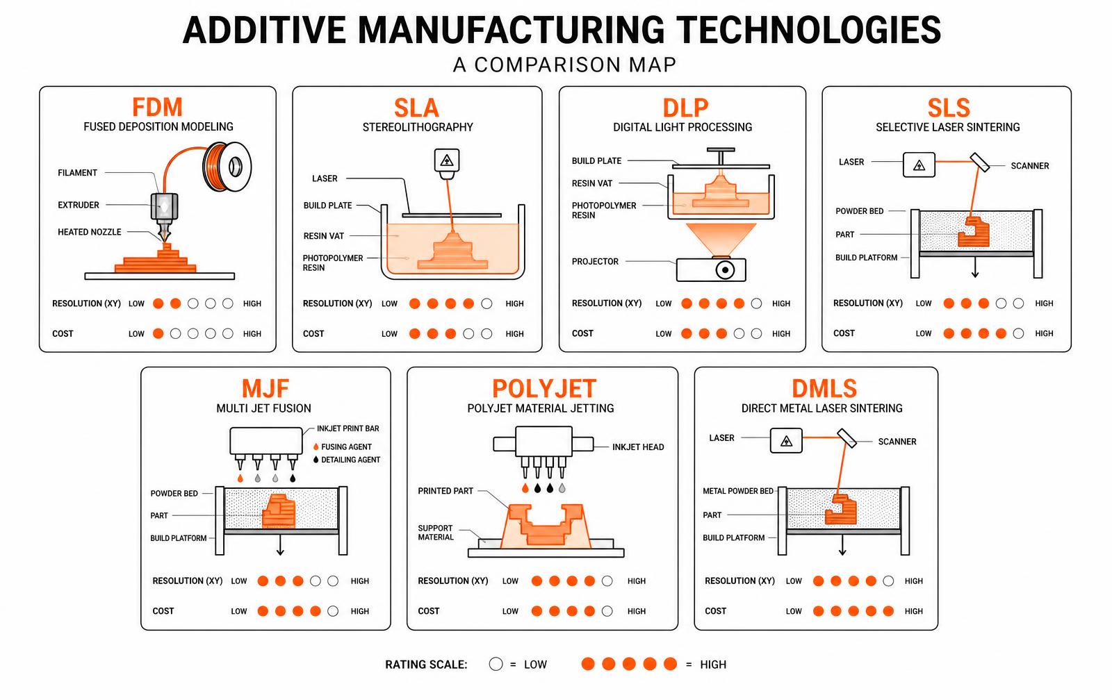
ISO/ASTM 52900 groups every additive process into seven categories. Vendor names change constantly; the categories do not, which makes them a stable way to compare quotes from different suppliers.
Process category | Common trade names | How a layer forms | Typical use |
|---|---|---|---|
Material extrusion | FDM, FFF | Thermoplastic filament extruded through a heated nozzle | Concept models, jigs, fixtures, large low-cost parts |
Vat photopolymerization | SLA, DLP, LCD | Liquid resin cured by a laser or projected light | Fine detail, smooth surfaces, casting patterns |
Powder bed fusion, polymer | SLS, MJF | Nylon powder fused by laser or by fusing agent and heat | Functional plastic parts and short production runs |
Powder bed fusion, metal | DMLS, SLM, EBM | Metal powder melted by laser or electron beam | Load-bearing metal parts, lightweighting, conformal cooling |
Material jetting | PolyJet, MJP | Droplets of photopolymer jetted and cured | Multi-material and multi-color prototypes, overmold simulation |
Binder jetting | Metal and sand binder jetting | Binder printed into powder, then sintered or cast | High-volume metal parts, sand casting molds |
Directed energy deposition | DED, LMD | Metal fed into a melt pool | Repair, cladding, large near-net shapes |
Choosing by what the part has to do
Most selection mistakes come from starting with the machine instead of the requirement. Work in this order: function, then material, then tolerance and finish, then quantity. Cost falls out of those four.
If the part must... | Choose | Why |
|---|---|---|
Look right in a review meeting | SLA or DLP | Smoothest as-printed surface, crisp features |
Survive functional testing in plastic | SLS or MJF | Isotropic nylon parts, no support marks, snap fits and living hinges hold |
Be cheap, big and quick | FDM | Lowest cost per cubic inch, widest machine availability |
Combine rigid and rubber-like sections | PolyJet | Multi-material in a single build, useful for gaskets and grips |
Carry structural or thermal load in metal | DMLS or SLM | Dense metal parts with near-wrought properties after heat treatment |
Reach hundreds or thousands of identical units | MJF or binder jetting | Highest throughput per build, most predictable unit cost |
Where the cost actually comes from
- Build volume occupied, not part count. Powder bed processes charge for the space and the powder cycle, so nesting many small parts in one build is dramatically cheaper per unit than printing them one at a time.
- Height in the build. Layer count sets machine time. A part laid flat can cost a fraction of the same part printed upright.
- Support structures. SLA, FDM and metal powder bed all need supports; removing and finishing them is manual labor that often exceeds the machine cost. SLS and MJF need none.
- Post-processing. Dyeing, vapor smoothing, media blasting, heat treatment and machining of critical features are separate operations with their own lead times.
- Material. Engineering resins, glass-filled nylons and metal powders can be several times the cost of standard grades.
Additive manufacturing is not cheap because printing is cheap. It is cheap because there is no tooling. The moment your quantity justifies a mold, the arithmetic flips.
When additive beats tooling, and when it does not
Additive has no tooling cost and a flat unit cost: the thousandth part costs roughly what the first one did. Injection molding has a large tooling cost and a very low unit cost. The crossover for a small plastic part is commonly in the hundreds to low thousands of units, depending on part size and mold complexity. Below the crossover, print. Above it, tool. Our breakdown of tooling economics works through where that line sits.
There is also a middle path that many teams miss: print the parts while the tool is being cut. Additive covers the first few hundred units for pilot builds, regulatory samples and early customers, which lets a launch date hold even when tooling slips. That is a routine part of our low-volume manufacturing work.
Designing for additive rather than adapting to it
- Wall thickness. Respect each process minimum: roughly 1 mm for SLS and MJF, 0.8 to 1 mm for SLA features, more for metal.
- Orientation and anisotropy. Extruded parts are weakest between layers. Orient so that loads run within a layer, not across the bond.
- Overhangs. Keep unsupported angles above about 45 degrees where the process needs supports, or accept the finish penalty.
- Trapped powder and resin. Hollow geometries need escape holes, or you pay for material you cannot recover.
- Critical fits. Do not expect a printed hole to be a bearing fit. Print undersize and machine or ream the features that matter.
- Consolidation. Additive rewards combining assemblies into one part, which removes fasteners, tolerance stacks and assembly labor.
Additive in production, not just prototyping
Production use is now routine in three places: end-use parts where geometry is impossible to mold, such as conformal cooling channels and lattice structures. Tooling and fixturing on the factory floor, where a printed jig costs a fraction of a machined one. And personalized products such as dental aligners and hearing aid shells, where every unit is different by definition.
The regulated end of that spectrum is well documented by the FDA guidance on 3D printed medical devices, which is worth reading before you plan an additive route for medical device manufacturing.
Frequently asked questions
What are the main additive manufacturing technologies?
ISO/ASTM 52900 defines seven categories: material extrusion, vat photopolymerization, powder bed fusion, material jetting, binder jetting, directed energy deposition and sheet lamination. In practice, most commercial work runs on four of them, FDM, SLA and DLP, SLS and MJF, and metal powder bed fusion.
Which 3D printing technology is strongest?
For plastics, powder bed fusion, SLS and MJF, gives the most consistent strength in all directions because there are no layer bonds weakened by supports. For load-bearing parts, metal powder bed fusion in aluminum, steel or titanium approaches wrought properties after heat treatment.
How accurate are additive parts?
Typical as-printed tolerances run about plus or minus 0.2 to 0.3 mm for SLS and MJF, and plus or minus 0.1 to 0.15 mm for SLA on small features, with metal processes similar before machining. Treat those as guidance, confirm with your supplier, and machine any feature that needs a tighter fit.
Is additive manufacturing cheaper than injection molding?
Below the crossover volume, yes, because there is no tooling to pay for. Above it, no, because additive unit cost stays flat while molded unit cost keeps falling. For a small plastic part the crossover typically sits somewhere in the hundreds to low thousands of units.
Can 3D printed parts be used in final products?
Yes. Additive parts ship in aerospace brackets, dental and hearing devices, custom orthotics and factory tooling. What production requires is process control: a qualified material, a fixed machine and parameter set, defined post-processing and inspection, exactly as with any other manufacturing process.
Sources and standards
- ISO/ASTM 52900 — terminology and the seven additive process categories.
- NIST additive manufacturing program — measurement science, qualification and process control research.
- FDA, 3D printing of medical devices — regulatory expectations for additive parts in devices.
Choosing between additive processes for a production part
Most additive manufacturing technologies can make a part that looks right. Far fewer can make the same part five hundred times with a tolerance band and a mechanical property you are willing to put on a drawing.
The selection question for production is therefore not which process prints fastest, but which process has the narrowest gap between a first article and the thousandth part.
That gap is driven by three things: how tightly the machine controls energy input, how much of the final geometry depends on support strategy, and how much post-processing a finished part still needs before it is dimensionally stable.
Powder bed fusion in nylon gives the best combination of isotropy and unattended throughput for enclosures, ducting and brackets, but it introduces a powder refresh ratio that must be specified or parts drift in colour and toughness across build campaigns.
Stereolithography and its resin derivatives hold the finest features and the crispest sealing surfaces, yet they age: an unfilled photopolymer that passes a drop test at week one can fail at month six after UV exposure.
Fused deposition holds up structurally in glass or carbon filled grades and is the cheapest route to large parts, but it is the most anisotropic of the three, so orientation becomes a controlled drawing note rather than an operator choice.
Metal powder bed fusion earns its cost only where the part consolidates several machined and welded components, or where an internal channel simply cannot be produced any other way.
Process | Best production fit | Main risk to control |
|---|---|---|
SLS / MJF nylon | Enclosures, ducts, brackets, 50-5,000 pcs | Powder refresh ratio and build-to-build colour drift |
SLA / DLS resin | Fine features, sealing faces, optical parts | UV and humidity ageing of mechanical properties |
FDM (filled grades) | Large structural parts, jigs, fixtures | Anisotropy; layer adhesion in the Z axis |
Metal PBF | Consolidated assemblies, internal channels | Residual stress, support removal, post-machining datums |
A practical rule: pick the process during design, not after. Once the wall sections, draft, bosses and datum scheme are drawn for one additive process, moving to another usually means a redesign rather than a re-quote. Lock the process, freeze the parameter set with the vendor in writing, and require witness coupons on every build so the qualification you paid for stays valid over the life of the programme.
Qualifying an additive part for production use
Using additive manufacturing technologies for production, rather than prototyping, changes the question from "does this part work" to "will every part work". Layer-based processes vary with machine, orientation, build position and powder history, so qualification has to lock those variables down the way any other process specification would.
Variables to fix in a production additive spec
Variable | Why it matters | How to control it |
|---|---|---|
Build orientation | Strength is anisotropic | Fix orientation in the process document |
Position on the plate | Thermal history varies across the bed | Define allowed zones or nest layout |
Powder reuse ratio | Affects mechanical properties | Specify virgin/recycled blend and cycles |
Machine and parameter set | Different machines give different results | Qualify per machine, list approved equipment |
Post-processing | Heat treat, HIP, surface finish | Specify each step and its acceptance |
Support removal | Witness marks and dimensional effects | Define support strategy and finish requirement |
Add witness coupons to every build and test them. That single practice turns a variable process into a monitored one, and it is what most customers and auditors expect to see before accepting additive parts in a finished product.
Production readiness checklist
- Document orientation, machine and parameters as a frozen process.
- Test witness coupons per build for tensile and density.
- Define the powder lot and reuse policy in writing.
- Establish dimensional inspection points, not just a visual check.
- Qualify a second supplier if the part is on the critical path.
Key takeaways
- Additive in production requires a frozen, documented process, not just a good print.
- Orientation, plate position and powder reuse all change part properties.
- Witness coupons per build are the standard evidence of consistency.
Considering additive manufacturing for production parts?
Work with LA NPDT: if you are moving from here to execution, start with our rapid prototyping services or talk to us about prototype design.
Filed under:EducationUncategorized
Tagged:2025
Services related to this guide
- Best prototyping companiesDevelopment firms, instant-quote bureaus and local shops — who fits which job.
- Free prototype cost calculatorFive to eight questions, an instant cost range for a first prototype.
- Prototype development companiesWhich firms take a sketch to a working prototype — and which only fabricate parts.
- Rapid prototypingWorking prototypes in days, from 3D printing to vacuum casting.