Industrial Design Software: The Stack From Sketch to Production
No single tool covers industrial design. Here is the four-layer stack, what each layer is for, what it costs, and how to hand files off without losing intent.
March 13, 20255 min read

Written by Konstantin Dolgan, Ph.D., NPDP
Founder & CEO, Product Development Engineer
Published March 13, 2025Updated September 2, 2026
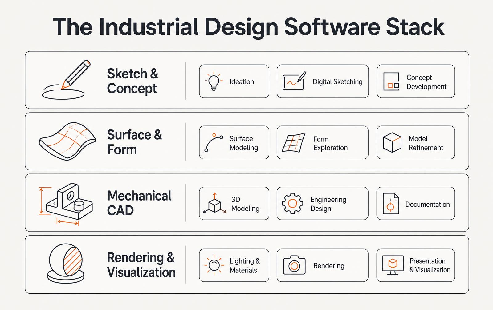
No single package covers industrial design end to end. Working studios run a four-layer stack: sketching, surface and form, mechanical CAD, and rendering. The skill that matters is not mastering one tool - it is moving geometry between layers without losing design intent or manufacturability.
Layer 1: Sketch and concept
Digital sketching on a tablet remains the fastest way to explore form. Twenty sketches in an afternoon beats one modeled concept in a week, because the purpose at this stage is to reject directions cheaply. Keep sketches at real proportion by tracing over a scale block so the shape you fall for is actually buildable.
Layer 2: Surface and form modeling
Class-A surfacing tools build continuous, curvature-smooth geometry that parametric CAD struggles to produce. Subdivision modeling is faster for organic exploration; NURBS surfacing is what survives into production. Whatever the tool, judge the model with zebra stripes and curvature combs, not with a pretty render.
Layer 3: Mechanical CAD
- Parametric history is where wall thickness, draft, bosses, ribs and tolerances live.
- Assemblies and mates catch interference before parts are ordered.
- Drawings with GD&T are what a supplier is legally quoting against.
- PDM or versioned storage prevents the two-people-editing-the-same-part failure.
- This is the layer that produces the release package: STEP, drawings, BOM.
Layer 4: Rendering, simulation and validation
Tool type | Used for | When it pays |
|---|---|---|
Photoreal rendering | Buyer research, packaging, retail decks | Before tooling, to test appeal cheaply |
Animation | Assembly instructions, mechanism review | Complex mechanisms and service procedures |
FEA structural | Stress, deflection, drop simulation | Any load-bearing or drop-critical part |
Mold flow | Fill, weld lines, warp prediction | Before cutting an expensive mold |
Thermal / CFD | Heat dissipation, airflow, sealing | Electronics inside a sealed enclosure |
What the stack costs
Layer | Typical annual license range | Notes |
|---|---|---|
Sketching | $0-$250 | Tablet app plus hardware is the real cost |
Surface / subdivision | $500-$3,500 | Some free or indie tiers exist |
Mechanical CAD | $1,500-$5,000 | Cloud tiers cheaper, feature-limited |
Rendering | $0-$1,500 | Often bundled with CAD |
Simulation | $2,000-$25,000 | Per-solver pricing, frequently outsourced |
For a small team, budget $4,000-$12,000 per seat per year for a workable stack, and outsource simulation until the volume of analysis justifies a license. Software is rarely the constraint - the constraint is whether the person driving it understands manufacturing.
Handoff rules that prevent rework
- Send STEP for geometry and native files only if the recipient uses the same package.
- Ship a dimensioned drawing with tolerances; geometry alone does not communicate intent.
- Freeze units and origin early - a model built at the wrong scale wastes days downstream.
- Name and version files by release, not by date or initials.
- Include the BOM and finish callouts with the CAD, not in a separate email thread.
We work in this stack daily across 3D modeling and prototyping, and the projects that go smoothly are the ones where surfacing and mechanical CAD talk to each other from week one.
Frequently asked questions
What software do industrial designers use?
Most industrial designers use a tablet sketching app for concepts, a surface or subdivision modeler for form, a parametric mechanical CAD package for production geometry, and a rendering tool for visualization. Simulation is added for load, thermal or molding questions.
Do I need CAD if I have a designer?
Yes. Concept renders are not manufacturable data. A supplier needs parametric CAD with wall thickness, draft, tolerances and a dimensioned drawing before anything can be quoted or tooled.
What file format should I send a manufacturer?
Send STEP (AP214 or AP242) for geometry plus PDF drawings with dimensions, tolerances and finish notes. STL is only appropriate for 3D printed form models, because it carries no tolerance or feature information.
Is free CAD software good enough for a product?
Free and hobby tiers can carry early concept work, but licensing terms often restrict commercial use and export options are limited. For anything heading to tooling, use a package that exports clean STEP and supports proper drawings.
Choose the stack around the handoff, not the demo
Industrial design software arguments usually happen at the wrong level. The question that matters is not which tool renders best; it is what happens at the handoff between concept form and engineering intent. A stack that produces beautiful concepts and unusable geometry costs weeks of remodelling, and that cost is invisible until the first engineering sprint.
The practical rule: pick a form-creation tool that exports clean solids or high-quality surfaces, pick a parametric CAD tool the manufacturing chain already speaks, and be honest about the translation step between them.
Where each category fits
Category | What it is for | Representative tools | Handoff quality |
|---|---|---|---|
Sketch and ideation | Fast visual exploration | Tablet sketching, concept boards | Reference only |
Sub-D and polygon modelling | Organic form, fast iteration | Blender, Modo, Sub-D in CAD | Needs conversion to NURBS |
NURBS surfacing | Class-A surfaces, complex transitions | Rhino, Alias | Direct to engineering |
Parametric CAD | Engineering intent, assemblies, drawings | SolidWorks, Onshape, Fusion, Creo, NX | Native manufacturing data |
Rendering and visualisation | Reviews, marketing, pre-sales | KeyShot, Blender Cycles, V-Ray | Images and animation |
Motion and mechanism study | Kinematics, interference, timing | CAD motion, MSC Adams | Validated movement |
Simulation | Structural, thermal, flow, drop | Ansys, SolidWorks Simulation, Abaqus | Test-informing results |
PDM and version control | Who has the current file | PDM, Onshape versions, Git-like tools | Prevents rework |
The file exchange traps that cost the most time
- Mesh to solid conversion: an STL is a faceted approximation, and rebuilding it as a solid is remodelling, not importing.
- Imported dumb solids lose parametric history, so an engineering change means editing geometry rather than a dimension.
- STEP is the reliable neutral format for solids; IGES surfaces frequently arrive with gaps that must be stitched.
- Tolerance mismatch between packages creates sliver faces that fail later in CAM and mould-flow analysis.
- Units and origin drift between tools quietly break assembly mating and downstream fixturing.
- Appearance and material data rarely survive translation; expect to reassign for rendering every time.
Honest cost of a small hardware team's stack
Seat | Tool class | Annual cost per seat | Notes |
|---|---|---|---|
Industrial designer | Sub-D or NURBS surfacing | $1,000-2,000 | Rhino perpetual is unusually good value |
Industrial designer | Rendering | $1,000-2,500 | Some renderers bundle with CAD |
Mechanical engineer | Parametric CAD | $1,500-4,500 | Cloud CAD lowers IT overhead |
Mechanical engineer | Simulation add-on | $2,000-12,000 | Buy per project when usage is occasional |
Whole team | PDM or cloud data management | $300-1,500 | Cheapest rework prevention available |
Whole team | CAM (if machining in-house) | $2,000-8,000 | Only if you cut your own parts |
A three-person team can be fully equipped for roughly $12,000-20,000 per year. Teams frequently overspend on simulation licences that are used twice and underspend on data management, which is what actually prevents the expensive category of mistake — building to the wrong revision.
Motion design is a functional discipline, not decoration
Movement in a physical product communicates state and quality. A drawer that decelerates before close, a lid whose damped travel signals precision, a switch with a defined detent — these are engineered behaviours, and they are specified with the same rigour as a dimension. Motion study tools exist to make those behaviours predictable before parts are cut.
Behaviour | What the user reads from it | How it is engineered |
|---|---|---|
Damped close | Quality, care, safety | Rotary damper sized to mass and arm length |
Detent on a control | Confirmed input, no ambiguity | Cam profile and spring rate specified |
Progressive resistance | Precision and control | Friction and geometry, not tolerance stack luck |
Consistent hinge torque | Durability | Torque hinge specified with end-of-life value |
Silent operation | Premium positioning | Material pairing and clearance control |
Specify these values as requirements — closing time in seconds, actuation force in newtons, torque retained after a stated cycle count — and verify them on prototypes. Motion that is left to whatever the parts happen to do is the most common reason a product feels cheap despite good surfaces.
Picking a stack: a short decision guide
Situation | Recommended core | Why |
|---|---|---|
Consumer product, organic forms | Rhino or sub-D plus SolidWorks or Fusion | Form freedom with a manufacturable handoff |
Industrial equipment, large assemblies | SolidWorks, Creo or NX | Assembly performance and drawing tooling |
Distributed or contractor-heavy team | Onshape or Fusion | Versioning and access without a PDM project |
Regulated device | Established CAD plus formal PDM | Traceability and revision control are auditable |
Very early startup | Fusion plus Blender | Low cost, adequate for pre-tooling work |
More questions teams ask
Frequently asked questions
What industrial design software should a small hardware team use?
A surfacing or sub-D tool for form exploration, one parametric CAD package the manufacturing chain already uses, a renderer, and cloud or PDM version control. For most small teams that is Rhino or Fusion for form, SolidWorks, Fusion or Onshape for engineering, and KeyShot or Blender for visuals.
Is Blender usable for real product design?
For concept form, visualisation and animation, yes, and many teams use it happily. It is not a substitute for parametric CAD: mesh geometry has to be rebuilt as solids before tooling, and drawings, tolerances and assembly intent live in the CAD package.
Do we need simulation software in-house?
Not usually at first. Occasional structural or thermal work is cheaper to buy as a service, and results are better when an experienced analyst runs it. Bring it in-house when simulation happens weekly rather than a few times a year.
How do we avoid remodelling when moving from design to engineering?
Agree the exchange format and geometry standard before concept work begins, keep surfaces watertight, model at production scale with a shared origin, and have engineering review the first concept model early rather than at handoff.
How is motion specified so it feels the same on every unit?
As numbers with tolerances: closing time, actuation force, torque at end of life, and permitted variation. Specify the damper or hinge component by performance, verify on prototypes across the tolerance range, and include the values in incoming inspection. Work with LA NPDT: if you are moving from here to execution, start with our product design services or talk to us about concept design services .
Filed under:EducationUncategorized
Tagged:2025
Services related to this guide
- Product design servicesIndustrial design and CAD taken all the way to manufacturable files.
- Best industrial design firmsWhich studios take an idea from form to manufacturable hardware, and what they charge.
- Prototype designLooks-like, works-like or pre-production: what each proves and what it costs.
- Product development examplesReal projects we designed, prototyped and shipped.