Robotics Prototyping: Choosing Processes, Printers and Materials
How to match robotics prototype parts - load-bearing brackets, gearbox housings, grippers and covers - to the right process, printer and material.
March 5, 20256 min read

Written by Ashok Chintagunta, MS Computer Science, Louisiana Tech University
CTO & Software Engineer, AI and Automation
Published March 5, 2025Updated September 2, 2026
Pick the process before you pick the printer. Robotics prototypes mix parts with very different demands: brackets that carry load, gearbox housings that need tight fits, grippers that must survive thousands of cycles, and cosmetic covers. No single machine is best at all four, so the practical question is which processes belong in your shop and which parts to send out.
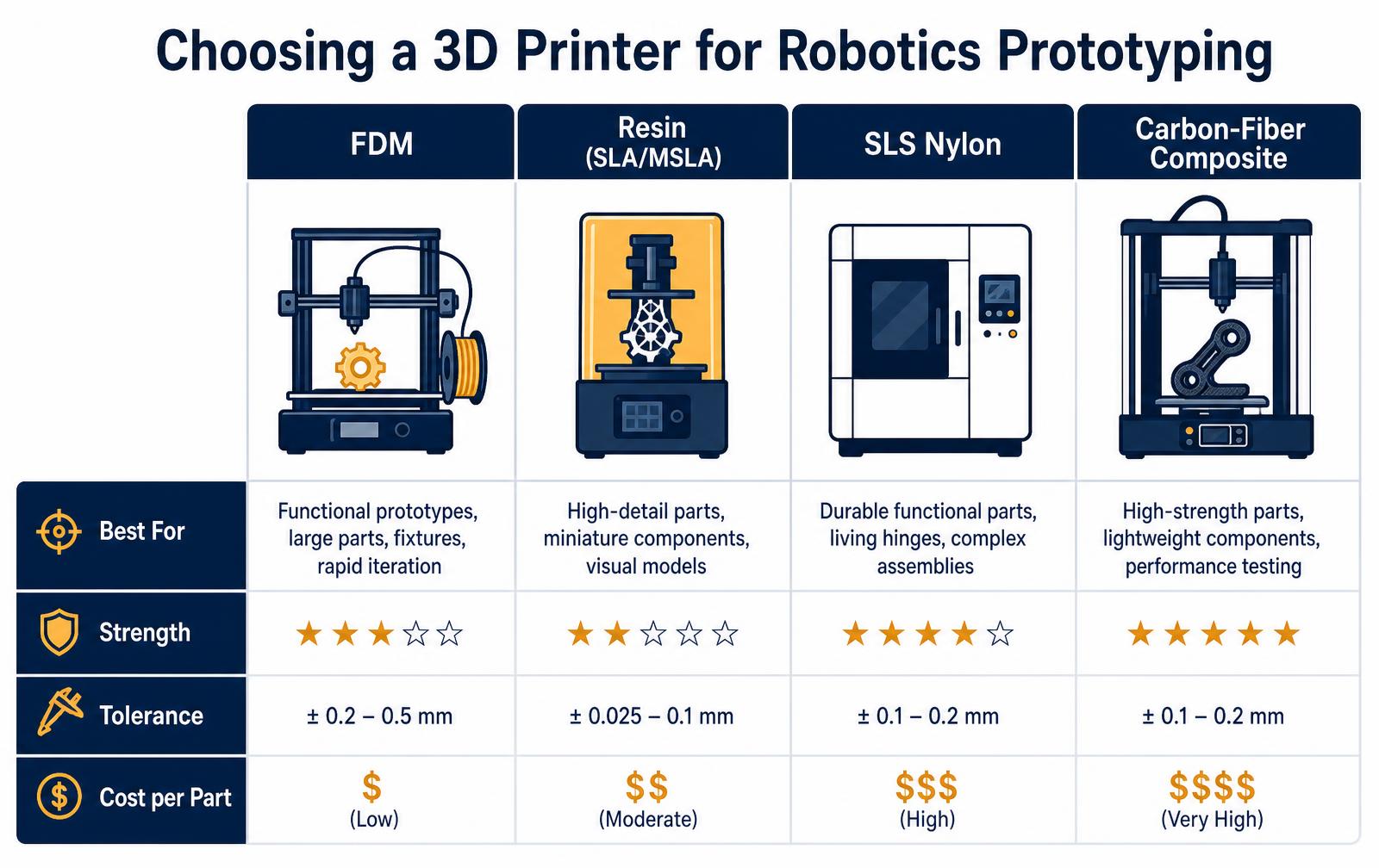
Process comparison for robot parts
Process | Best robot parts | Tolerance | Machine cost | Cost per part |
|---|---|---|---|---|
FDM | Brackets, fixtures, large covers, iteration parts | ±0.2-0.5 mm | $400-$6,000 | Low |
Resin (SLA/MSLA) | Small gears, sensor mounts, detailed visual models | ±0.025-0.1 mm | $300-$5,000 | Moderate |
SLS nylon | Grippers, living hinges, cable guides, snap fits | ±0.1-0.2 mm | $18,000+ or outsource | High |
Carbon-fiber composite | Arm links, load-bearing structure, end effectors | ±0.1-0.2 mm | $4,000-$70,000 | Very high |
A practical shop setup
- One workhorse FDM machine with a hardened nozzle and enclosed chamber so it can run PETG, ABS, PC and glass-filled nylon, not just PLA.
- One desktop resin printer for small precision parts, sensor housings and gear prototypes where surface finish and fine features matter.
- A service bureau relationship for SLS and composite parts instead of buying the machine, until you are printing functional nylon weekly.
- Machined or moulded parts for anything under continuous load, high temperature or sealing duty; printing buys iteration speed, not every final part.
Specs worth checking, and specs to ignore
Advertised layer height and top speed tell you very little about whether a printer suits robotics work.
What matters is repeatability across the build plate, chamber temperature control for warp-prone engineering filaments, nozzle temperature ceiling for materials such as PC and PA-CF, and how easily you can hold a fit within a tenth of a millimetre after calibration.
For load-bearing parts, print orientation matters more than machine brand, because layer adhesion is the weakest axis in every extrusion process.
Related reading: our rapid prototyping services and how to cut 3D prototype costs.
Matching robot parts to a print process
Part | Best process | Material | Why |
|---|---|---|---|
Structural brackets | MJF or SLS | PA12 / PA12-GF | Isotropic strength, no supports |
Gripper fingers | SLA or MJF | Tough resin / TPU | Detail plus compliance where needed |
Gearbox housings | SLS or CNC | PA12 / aluminum | Dimensional stability under load |
Cable guides and clips | FDM | PETG | Cheap, fast, easily iterated |
Sensor mounts | SLA | Rigid 10k resin | Tight tolerance and flatness |
Heat-adjacent parts | SLS or DMLS | PA12-CF / aluminum | Higher HDT than standard resins |
Tolerance and design rules worth memorizing
- Plan for +/-0.3% dimensional accuracy on SLS and MJF, and machine or ream any bearing bore.
- Print threads as clearance holes and add heat-set inserts. Printed threads strip under robot vibration.
- Orient parts so load runs across layers, not along them, on FDM especially.
- Keep walls at or above 1.5 mm for nylon powder parts; thinner sections warp during cooling.
- Design a datum feature into every prototype so repeat prints assemble the same way.
- Budget post-processing time. Depowdering, dyeing and reaming often exceed the print time itself.
Print Settings That Decide Whether a Robotics Part Survives Testing
Process choice gets most of the attention, but on robotics hardware the failure usually traces back to a handful of print parameters. Layer orientation is first: printed parts are weakest across layer lines, so any bracket, arm, or mount should be oriented so that the dominant load runs in-plane rather than pulling layers apart. Re-orienting a part costs nothing and routinely doubles effective strength.
Wall count matters more than infill for structural parts. Four to six perimeters with 25–35% gyroid infill outperforms a thin-walled part packed to 80% at similar mass and print time. For bolted joints, design in metal heat-set inserts rather than tapping printed threads — printed threads strip under the preload a robot joint sees within a few assembly cycles.
Watch temperature and duty cycle. Motor mounts and gearbox housings sit against heat sources, and standard PLA loses stiffness near 55 °C. Move to PETG, ABS, PA12 nylon, or a carbon-filled nylon for anything mounted to a continuously driven actuator. For SLS and MJF nylon parts, allow for anisotropic shrink and moisture uptake — dimension critical bores as post-machined features rather than trusting as-printed tolerance.
Finally, print the test coupons alongside the part. A tensile bar and a bolt-boss coupon from the same build give you real numbers for the machine, material lot, and orientation you actually used, which is far more useful than a datasheet value when you are deciding whether to move a subassembly to a machined or molded part.
Frequently asked questions
What is the best 3D printer for robotics prototyping?
For most robotics teams an enclosed FDM printer that handles engineering filaments such as PETG, ABS, PC and carbon-filled nylon covers the majority of parts. Add a desktop resin printer for small precision components, and outsource SLS nylon or continuous-fiber composite parts until volume justifies buying the machine.
Which material is strongest for printed robot parts?
Carbon-fiber reinforced nylon gives the best stiffness-to-weight for arm links and structural brackets, while SLS nylon is the most durable choice for grippers, snap fits and living hinges because it lacks the pronounced layer-adhesion weak axis of extrusion. Orientation still governs strength: load should run along the layers, not across them.
How much should a robotics prototyping printer cost?
A capable enclosed FDM machine runs $1,500 to $6,000 and covers most iteration work. A desktop resin printer adds $300 to $5,000. SLS systems start around $18,000 and composite printers around $4,000, which is why most teams outsource those parts at $30 to $200 each until weekly demand appears.
Choosing processes and materials for robotics prototyping
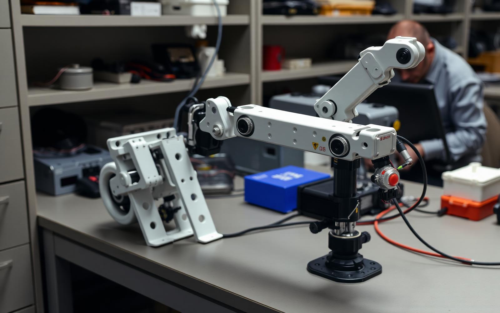
Robotics prototyping punishes the wrong material choice faster than most disciplines, because parts see continuous cyclic load, heat from motors, and impacts from the inevitable crash. The rule of thumb: printed parts are fine for brackets, covers and grippers, but anything carrying a bearing preload, a belt tension or a gearbox reaction should be machined metal by the second prototype.
Material / process | Best use in robotics | Strength | Cost per part | Watch out for |
|---|---|---|---|---|
PLA (FDM) | Fit checks, jigs | Low | $5-$40 | Creeps and softens near motors |
PETG / ABS (FDM) | Covers, non-structural brackets | Medium | $8-$60 | Layer adhesion in the Z axis |
Nylon with carbon fibre (FDM) | Structural brackets, gripper fingers | High | $25-$180 | Moisture absorption before printing |
SLS nylon (PA12) | Complex housings, living hinges | High | $40-$300 | Porous surface needs sealing |
SLA resin | Optical mounts, appearance parts | Low to medium | $20-$200 | Brittle and UV sensitive |
Machined aluminum | Bearing mounts, arm links | Very high | $80-$900 | Lead time and cost per iteration |
A prototyping sequence that avoids rework
- Kinematic mock-up. Printed links with off-the-shelf bearings to prove reach and collision envelope before anyone sizes a motor.
- Actuator sizing rig. Measure real torque with a load cell instead of trusting the datasheet duty cycle.
- Structural iteration. Replace printed load paths with machined parts and measure deflection under static load.
- Harness and cable management. Route the real harness early; cable routing kills more designs than stiffness does.
- Endurance run. A few hundred thousand cycles on the bench exposes fastener loosening, belt stretch and gear wear before a customer does.
- Safety and E-stop. Design the stop circuit as hardware in the first integrated prototype, not as firmware later.
Where printed parts genuinely belong in a shipping robot
Additive is not just a prototype tool. In low-volume industrial robotics, SLS nylon end effectors, sensor brackets and cable guides are commonly shipped, because tooling cannot be justified below a few thousand units and the geometry changes per customer. The discipline is to qualify those parts the same way you would a molded one: material certificate, print parameters locked, and a dimensional check on every batch.
- Key takeaway 1: Print brackets and covers; machine anything carrying bearing or gearbox loads.
- Key takeaway 2: Size actuators from measured torque, not from datasheet ratings.
- Key takeaway 3: Route the real harness in the first integrated build.
- Key takeaway 4: Printed production parts are viable when qualified with locked parameters and batch inspection.
Post-processing printed robot parts
A printed bracket is rarely finished when it comes off the plate. Robots load their parts in ways that expose exactly the weaknesses printing introduces: layer adhesion in tension, soft holes at bearing seats, and threads that strip on the third service cycle. Planning post-processing during design is what separates a printed part that survives a demo from one that survives a pilot fleet.
Post-process operations, time and cost
Operation | Applies to | Time per part | Typical cost |
|---|---|---|---|
Support removal and sanding | FDM, SLA | 10-40 min | Labor only |
Heat-set threaded inserts | FDM, SLS | 1-3 min per insert | $0.15-$0.60 per insert |
Reaming or boring bearing seats | All | 5-15 min | Shop rate, needs a fixture |
Annealing (PA, PC, PPS) | FDM, SLS | 2-6 hr batch | Oven time; expect 1-2% shrink |
Vapor smoothing | SLS nylon | Batch | $3-$12 per part |
Epoxy or resin sealing | SLA, FDM | 30 min + cure | Needed for fluid or dust exposure |
Design for these steps rather than adding them later: put a 0.2-0.3 mm machining allowance on bores that must be round, model insert bosses to the manufacturer's hole chart, and orient parts so the primary load runs across layers instead of pulling them apart.
Rules that prevent rework
- Never print a load-bearing thread — use heat-set inserts or captive nuts.
- Orient so the highest tensile stress is in-plane, not along the Z axis.
- Add ribs instead of wall thickness; thick walls warp and waste print time.
- Anneal before final machining, because parts move during the cycle.
- Keep one printed and one machined version of any part that will see a fleet trial.
Key takeaways
- Post-processing is part of the part cost and should be quoted with the print.
- Inserts, reaming and annealing fix the three failure modes robots find first.
- Design for orientation and allowance up front; it is free at CAD stage and expensive later.
Need robot parts prototyped fast?
We print, machine and test functional robotics hardware in-house.
Work with LA NPDT: if you are moving from here to execution, start with our rapid prototyping services or talk to us about prototype design.
Filed under:EducationUncategorized
Tagged:2025
Services related to this guide
- Best prototyping companiesDevelopment firms, instant-quote bureaus and local shops — who fits which job.
- Free prototype cost calculatorFive to eight questions, an instant cost range for a first prototype.
- Prototype development companiesWhich firms take a sketch to a working prototype — and which only fabricate parts.
- Rapid prototypingWorking prototypes in days, from 3D printing to vacuum casting.