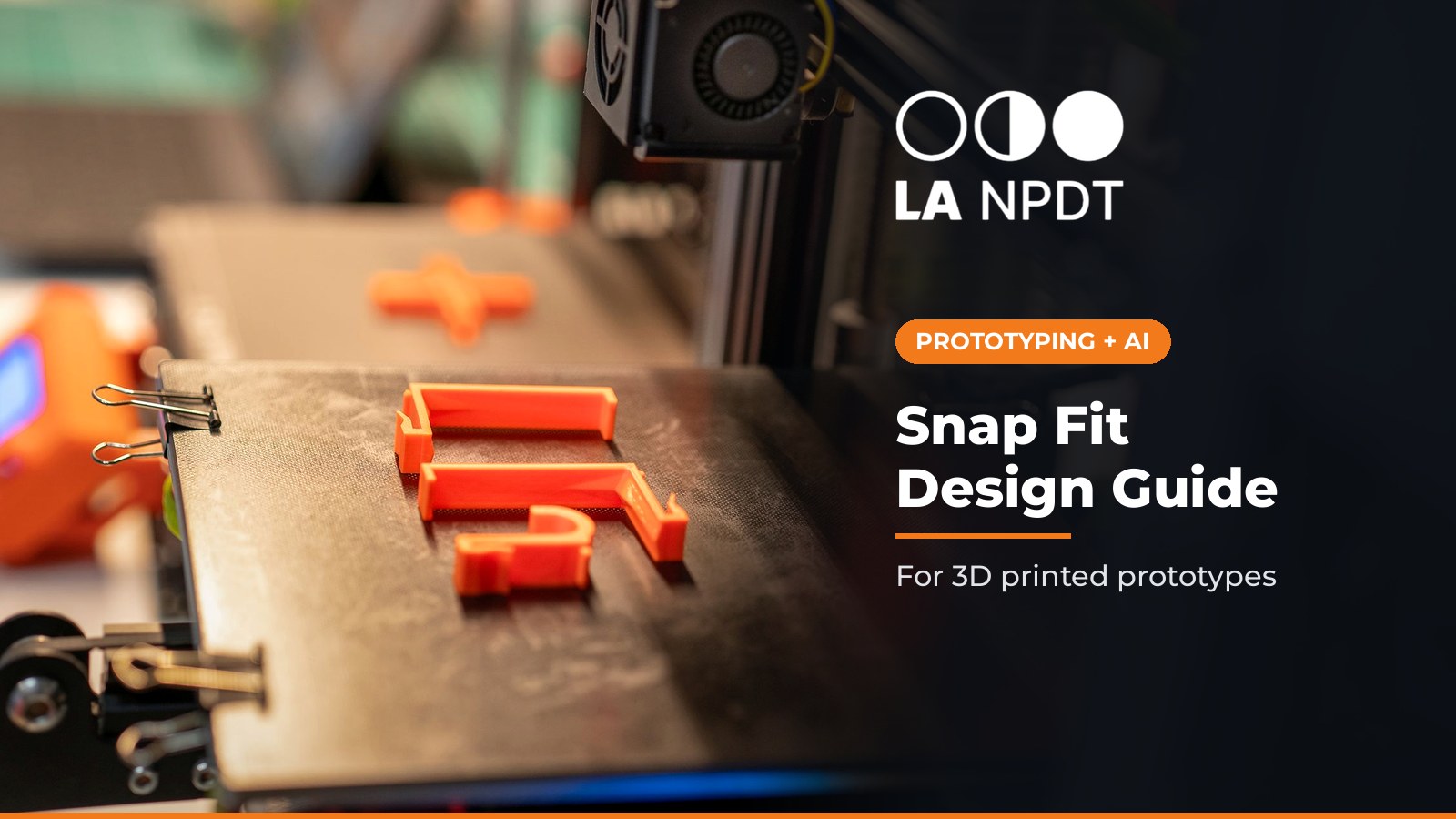
Snap fit design guide: 3D printed snap fits that survive prototype builds
A clip that snaps once on the bench and cracks on the third opening is a design problem, not bad luck. Here is how we size cantilever snap fits for printed prototypes, with the math shown, and what changes when the same part goes to a mold.
November 18, 20268 min read

Written by Konstantin Dolgan, Ph.D., NPDP
Founder & CEO, Product Development Engineer
Published November 18, 2026
What is a snap fit?
A snap fit is a joint where one part has a flexible protrusion, such as a hook, bead or stud, and the mating part has a recess or ledge that catches it. During assembly the protrusion deflects, then returns to its resting shape and locks behind the undercut.
The engineering guide "Snap-Fit Joints for Plastics" from Bayer MaterialScience describes all snap joints as sharing this principle: a protruding part of one component is briefly deflected during joining and catches in a depression in the mating part (Snap-Fit Joints for Plastics: A Design Guide).
For a product team, snap fits mean fewer screws, faster assembly, and a lid that can open for service. For a prototype, they also mean one more feature that can crack, creep or rattle if it is sized by eye.
Types of snap fits you will see on a prototype
- Cantilever snap fit: a beam with a hook at the tip. The most common type on enclosures and battery doors, and the easiest to calculate.
- Torsional snap fit: the latch rotates on a small torsion bar instead of bending. Useful when you want a lever you press to release.
- Annular snap fit: a ring that stretches over a bead, like a pen cap or bottle cap. Protolabs Network notes that with the right geometry and material an annular joint can even give a watertight seal (Protolabs Network: snap-fit joints for 3D printing).
The rest of this guide focuses on the cantilever, because it is the one most product teams put on a first prototype.
Cantilever snap fit math: the one check that matters
The arm fails when the strain at its root is too high. For a rectangular arm of constant thickness, the design guide gives the permissible deflection as:
y = 0.67 x ε x L² / h
where y is the deflection (equal to the undercut depth), ε is the strain at the root (as a decimal), L is the arm length and h is the thickness at the root. Rearranged for strain: ε = y x h / (0.67 x L²).
If the arm tapers linearly to half its thickness at the tip, the factor rises from 0.67 to 1.09. The guide states that this tapered design increases the permissible deflection by more than 60% compared with a constant cross section, and recommends it whenever possible (Snap-Fit Joints for Plastics).
Worked example: a cantilever clip on a printed enclosure lid
The numbers below are illustrative, chosen to show the method. They are not a material recommendation.
A lid clip printed in a tough FDM material: arm length L = 12 mm, root thickness h = 1.6 mm, width 6 mm, undercut y = 1.0 mm.
Version | Change | Root strain |
|---|---|---|
A | Constant thickness, L = 12 mm | 1.0 x 1.6 / (0.67 x 144) = 1.66% |
B | Same arm, tapered to 0.8 mm at the tip | 1.0 x 1.6 / (1.09 x 144) = 1.02% |
C | Constant thickness, arm lengthened to 16 mm | 1.0 x 1.6 / (0.67 x 256) = 0.93% |
Strain scales with the square of length, so a few extra millimeters of arm does more than any other change. Tapering gets most of the same benefit without needing more room inside the enclosure.
What do you compare that strain to? The design guide's limits are for molded engineering resins, for example 4% for polycarbonate and 2.5% for a PC/ABS blend for a single assembly, and it says to use about 60% of those values when the joint will be opened and closed often.
Its own worked example sizes the hook to half the permissible strain.
Those limits are for molded resins and do not transfer directly to printed parts, which Protolabs Network notes are weaker across layers because of anisotropy, so for a printed prototype we take the printed material's datasheet values, stay well below them, and then confirm with a few test prints that we open and close many more times than the product will see in a demo.
3D printed snap fits: process rules that change the answer
- Clearance: Protolabs Network recommends a nominal clearance of 0.5 mm for FDM and 0.3 mm for SLA, SLS and MJF, while noting there are no universal tolerance rules because printers and materials vary (Protolabs Network). If the snap sits inside a longer chain of parts, run a tolerance stack-up on it.
- Print orientation: avoid building the cantilever vertically in Z. Layer bonding makes printed parts weakest across layers, and a vertical arm bends exactly across those layers.
- Fillet the root: Protolabs Network suggests a fillet radius of at least 0.5 times the base thickness. The molded-plastics guide shows that stress concentration drops sharply up to a radius of about 0.6 times the thickness, with little gain after that, and says the radius should never be less than 0.015 in (about 0.4 mm).
- Width: Protolabs Network recommends at least 5 mm of clip width for 3D printed snap fits, and adding locating lugs so the clips retain the part while the lugs carry shear.
- Material: tough, ductile materials such as ABS, PETG and nylon (PA12) suit snap fits; PLA and standard SLA resins are more brittle. SLS and MJF nylon are the usual choice when a printed snap must cycle many times (Protolabs Network). Our prototype material guide covers the wider trade-offs.
- Rest unloaded: the arm should only be bent during assembly and return to neutral once engaged. A clip that stays bent will creep and loosen over time.
From printed prototype to molded part: what changes
A printed snap fit ignores most molding constraints, which is why it is great for fast iteration and also why it can hide problems. Protolabs explains that snap features are undercuts, and in a simple straight-pull mold they typically need a pickout insert or a lifter, which adds tool cost and lead time. One common workaround is a pass-through core that needs a hole in the part under the hook (Protolabs: designing complex injection molding features).
In practice we ask three questions before a snap design is frozen:
- Which way does the mold open, and can this hook release in that direction?
- Is a relief hole under the hook acceptable for looks and sealing?
- Does the strain still work in the production resin, which may differ from the printed material?
These are part of a normal DFM review, and they also affect whether a short run makes sense in soft or hard tooling.
Where AI helps with snap fit design, and where it does not
AI CAD agents can now generate editable geometry from a prompt. Zoo, for example, describes its Zookeeper agent in Zoo Design Studio as creating fully editable 3D models from one prompt (Zoo Text-to-CAD). That is useful for drafting a clip family with a few lengths and tapers to print side by side. We covered what these tools do well and badly in AI CAD agents for prototypes.
Simulation, including newer AI-accelerated solvers, can show where the strain concentrates at the root before anyone prints. See physics AI and simulation in prototyping for how that fits next to physical tests.
What AI does not do for you: pick the right allowable strain for a printed, layered material, know how your product is opened in real life, or replace the open-close test on real parts. The formula above is simple enough that an engineer should always check the output by hand.
Snap fit design checklist for a prototype
- Define the job: permanent, occasional service, or opened every day.
- Pick the type: cantilever for most lids and doors.
- Calculate root strain for the undercut you need; taper or lengthen the arm before thickening it.
- Compare against the printed material's data with a healthy margin; reduce further for frequent opening.
- Add a root fillet, at least 5 mm width, and locating lugs.
- Set clearance for the process (about 0.5 mm FDM, about 0.3 mm SLA, SLS, MJF).
- Orient the arm flat on the build plate.
- Print a small test coupon of the clip before the full enclosure.
- Note how the hook will release from a mold if the part is headed to production.
How LA NPDT handles snap fits in a prototype program
On our rapid prototyping work, snap fits are reviewed together with the rest of the enclosure: wall thickness, bosses, sealing and the board inside, as covered in our enclosure design for electronics guide. We size the clip, print coupons, test them, and only then commit the full housing. If the product is headed to molding, the hook direction and release are checked before the design is frozen, not discovered by the toolmaker.
If you are at the idea or early CAD stage and not sure what comes first, our Stage 1 Review/Analysis + Plan is a fixed $800 single payment and lays out the path from concept to prototype. You can see where it sits in the process map and on the product development cost page, or book a free 20-minute call: Calendly: lanpdt initial consultation.
Want an engineer to size your snap fits before you print?
If you have a clip, latch or enclosure that needs to hold together, book a free 20-minute call with an engineer.
Sources
Frequently asked questions
What is a good snap fit design guide rule of thumb?
Keep the root strain low: make the arm as long as space allows, taper it toward the tip, add a root fillet, and size the undercut only as deep as retention needs. Then confirm with printed test coupons.
How do you design a 3D printed snap fit?
Use a tough material such as PETG, ABS or nylon, print the arm flat rather than vertical in Z, allow about 0.5 mm clearance for FDM or about 0.3 mm for SLA, SLS and MJF, and keep the arm at least 5 mm wide with a root fillet.
What is the formula for a cantilever snap fit?
For a rectangular arm of constant thickness, deflection y = 0.67 x strain x length² / thickness. If the arm tapers to half thickness at the tip, the factor becomes 1.09, which allows more than 60% more deflection at the same strain.
What material is best for 3D printed snap fits?
Ductile materials work best. SLS or MJF nylon (PA12) is the usual choice for snaps that cycle many times; PETG and ABS work for FDM. PLA and standard SLA resins are more brittle and crack sooner.
Why do 3D printed snap fits break?
Most failures come from too much strain at the root, a sharp internal corner, an arm printed vertically so it bends across layers, or a clip that stays bent after assembly and creeps.
Can a 3D printed snap fit go straight to injection molding?
Not always. A hook is an undercut, and in a simple mold it may need a lifter, a pickout insert or a relief hole under the hook. Review mold release direction and the production resin before freezing the design.
Services related to this guide
- Product design servicesIndustrial design and CAD taken all the way to manufacturable files.
- Best industrial design firmsWhich studios take an idea from form to manufacturable hardware, and what they charge.
- Prototype designLooks-like, works-like or pre-production: what each proves and what it costs.
- Product development examplesReal projects we designed, prototyped and shipped.