Designing for Manufacturability (DFM): Turning Concepts Into Production-Ready Products
Design for Manufacturability (DFM) transforms product concepts into production-ready designs by aligning engineering decisions with real-world manufacturing constraints. By integrating cross-functional collaboration early, DFM reduces cost, improves quality, enhances sustainability, and accelerates time to market.
January 28, 202610 min read

Written by Konstantin Dolgan, Ph.D., NPDP
Founder & CEO, Product Development Engineer
Published January 28, 2026Updated September 2, 2026
read 5 mins
Design for Manufacturability applies to products made in large amounts. You must design items for high volume methods. This stops low yields, defects, and high costs. It also protects the life of the product.
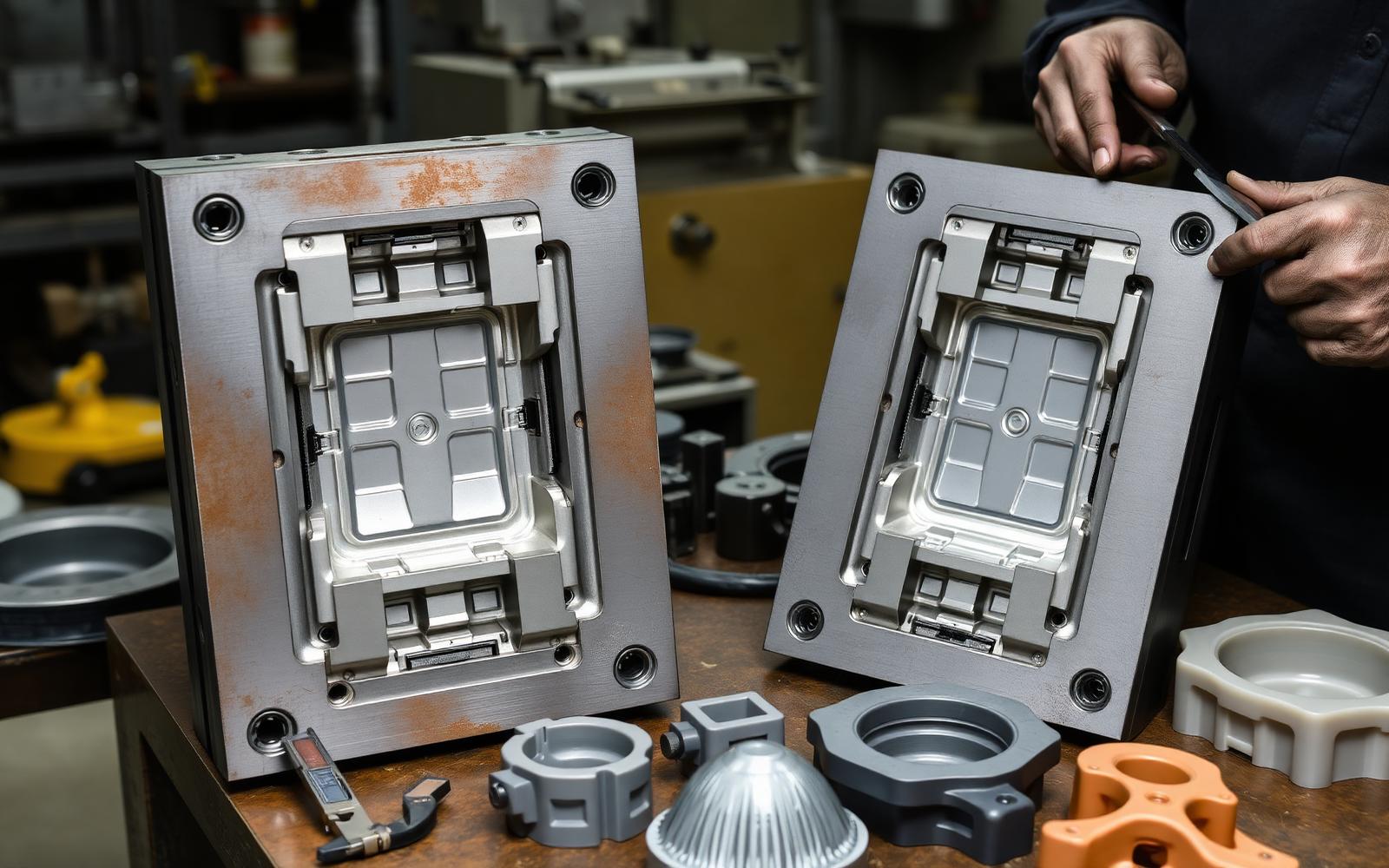
Design for Manufacturability (DFM) means making parts that are simpler to build. This makes them cheaper to produce. DFM makes sure products work well and are easy to make at scale.
Work culture and mindset shape what a firm can do. Long ago, engineers felt they knew how to build things. Many had very little time on the factory floor. They thought their job was to design and the plant would build it. This gap did not work.
Some people resisted when asked to work with factory staff. Some engineers felt they already knew the process well. History shows that teams working together get better results. This leads to much better product designs.
The Philosophy and Importance of DFM
DFM aims to make products that are easy to build in large amounts. These items have high manufacturability. DFM can focus on building, assembly, or yield. It may also cover testing, packing, or the environment.
DFM helps designers and process engineers talk and work together. You can use tools like CAD and planning software. Shared databases and digital tools also help these teams stay in touch.
Cost data shows why DFM matters. Design choices set about 70% of a product's cost. This covers materials, work, and assembly. Only 20% of cost comes from choices like machines or plans.
Manufacturability Defined
Manufacturability shows how well you can make a product. This depends on its design. It also depends on cost limits and shipping needs. Problems can come from one or more of these things.
Key Manufacturability Dimensions
- Overall Feasibility. A design might define a routing or process sequence. This sequence simply cannot be performed as described.
- Sustainability. Rules about carbon emissions are increasing. Consumer expectations are also rising. These drive new sustainability efforts. Early design choices and manufacturability decisions are key. They determine a product's environmental impact.
- Excess Cost. A design, once final, locks in the manufacturing process. Designers need tools to estimate costs. They also need to model manufacturing outcomes during design. This is important before release.
What Is Design for Manufacturability?
Design for manufacturability (DFM) is an engineering method. It makes products easy to build at a low cost. The parts still meet all needs for form, fit, and function.
Good DFM uses data for specific products and methods. This can include tolerance or cooling-time checks. It also looks at how to choose materials and machines. DFM helps keep quality high and costs low during development.
DFM sets quality rules for materials and assembly. It helps firms use fewer parts. The first design stage is the best time to use DFM. This leads to fewer reworks and faster sales at lower costs.
Typical DFM Activities
- We compare design choices. This helps find the option with the fewest manufacturing problems. It also aims for the lowest production cost.
- We find design features. These features might add unnecessary manufacturing steps. They could also hurt sustainability goals.
- We learn why supplier cost estimates are higher than expected. This helps us understand the reasons behind the expenses.
- We prevent manufacturing problems. This stops them from appearing late in the design process. It also avoids delays in launching products.
In the past, DFM analysis had limits. This was due to computing problems. Now, digital tools help us. They simulate manufacturing. This allows deep modeling of how things can be made. This was not possible before.
Dfma Tools and Supporting Systems
Design for Manufacturing and Assembly (DfMA) tools speed up sales. They also lower risk. These tools use teams from many fields instead of just one designer.
This method helps everyone share knowledge. It spans the product development cycle. It lets us fix problems and use feedback early. Design changes are cheaper and easier to make then.
The DFM Process Lifecycle
The DFM process typically follows a structured sequence:
- First, we create initial ideas. We also consider if they can be made. Next, we choose the right manufacturing methods. This depends on how many we make, what material we use, and how complex it is. Then, we refine the design. We add specific manufacturing details, like tool access and mold lines. We build and test prototypes. This helps us check if they can be made well. We use feedback from manufacturing. This makes the design better. Finally, we release the design for full production.
Figure 1. Product Quality Planning’s DfMA framework (Source – constructioninnovationhub.org.uk )
Figure 1. The DfMA framework for Product Quality Planning (Source –Org: 3 cpqp dfma final)
Contact us today to learn how LA NPDT can assist in realizing your project.
Contact us today to learn how LA NPDT can assist in realizing your project.
Purpose and Evolution of Dfma
As a comprehensive methodology, DfMA serves two main purposes:
- We support concurrent engineering studies. These studies simplify product structures. They also reduce manufacturing and assembly costs. We quantify these improvements.
- We provide a benchmarking framework. This framework evaluates competitor products. It also assesses how difficult manufacturing and assembly are.
DfMA helps firms make better goods for less money. Old methods used small teams with little shop-floor skill. This led to too many parts and complex work. Redesign work once wasted 30% of development effort.
To fix these issues, teams brought in suppliers and experts early in the process. DfMA gave them a clear way to measure how design choices affect production.
Key Benefits of DFM
- Early design choices greatly impact a product's environmental footprint. They affect up to 80% of its lifecycle impact. DFM finds manufacturing and sustainability risks before production starts.
- Advanced DFM tools offer useful suggestions. They don't just give warnings. This helps make small design changes to avoid big problems.
- DFM can find ways to cut costs for current products. It can also lower CO₂ emissions. Performance will not be reduced.
- Companies that outsource manufacturing can use in-house DFM. This speeds up development. It reduces the need for lengthy supplier feedback.
Core Principles of Design for Manufacturability
- Manufacturing Process Choice.
How things are made impacts costs and carbon emissions. A strong DFM plan looks at different ways to make things. It checks costs, delivery, and environmental impact.
- Design choices reflect manufacturing reality. Each decision shows this.
Tools help model manufacturing costs. They find what drives high costs. Examples include extra weight or high transport fees. They also flag processes needing a lot of labor.
- We choose components that are smart and modular. This makes them easy to use and change.
You can use standard or shared parts. This makes manufacturing simpler. It does not reduce quality. DFM helps compare standard parts to custom ones.
- Tolerances and specifications are based on requirements.
Specifying too much can raise costs. It may force expensive processes. DFM helps find the best fit. It balances needs with cost goals.
- Tooling Considerations
Tooling costs can make up most of the total build price. A slightly higher part cost might save money by cutting the need for extra tools. Additive manufacturing is one case where higher first costs lower lifetime costs and waste.
- Compliance and Testing.
In regulated industries, factor in compliance and testing costs. Do this for manufacturability analysis. This is very important as environmental rules get stricter.
DFM and Cross‑Functional Collaboration
DFM strengthens collaboration across organizations by:
- Allow other teams to give valuable design ideas. This helps shape engineering plans.
- Combine different types of knowledge. This creates more design choices.
- Find manufacturing and customer problems early. Address these issues before they grow.
- Reduce problems that happen during team handovers. Smooth transitions are key.
Practical Steps to Implement DFM
- Use DFM from the start.
Think about how easy something is to make and how sustainable it is right from the start. This gives you more chances to improve things. You will have few redesign choices once production tools are made. Good software helps you look closely at designs. It does not make development slower.
- Help teams develop products together effectively.
DFM helps designers, manufacturers, and suppliers work together. It does this whether manufacturing is done inside or by others. DFM finds problems early. It also makes sure things match sustainability goals.
- Integrate With Broader Cost Modeling.
Making things can be hard. It depends on weight, size, and materials. Tooling, labor, and overhead also play a part. Good Design for Manufacturability (DFM) is key. It must be part of a full cost plan.
The Role of Integrated Design Teams
The most vital part of Design for Manufacturability is a diverse product team. Working together makes sure designs are easy to build, cheap, and meet user needs.
These teams include people from design, quality, sales, and supply. You must set customer needs and costs early to avoid slow and expensive rework.
Conclusion
Design choices greatly affect how much a product costs to make and its environmental impact. We add manufacturing knowledge directly into the product design process. Our teams are experienced. They use structured Design for Manufacturability (DFM) methods. This makes production efficient. It also helps keep costs down.
Design for Manufacturability helps make products that work well and cost less. DFM rules will change as tools like AI and automation grow. In the end, DFM leads to faster builds, better yields, and lower total costs.
Subscribe
Dive deep into the dynamic world of new product development with LA NPDT Insights Blog.
Recent Posts
Geopolitical Risk in New Product Development
Component Lifecycle Management: Designing for Obsolescence
Material Qualification Strategy: Reducing Risk Before Production
Bridging Digital and Physical Prototyping
Systems Thinking in Hardware Development
You used Chatgpt to develop a product idea. Now what?
Subscribe
Dive deep into the dynamic world of new product development with LA NPDT Insights Blog.
Recent Posts
Geopolitical Risk in New Product Development
Component Lifecycle Management: Designing for Obsolescence
Material Qualification Strategy: Reducing Risk Before Production
Bridging Digital and Physical Prototyping
Systems Thinking in Hardware Development
You used Chatgpt to develop a product idea. Now what?
The DFM Process Lifecycle Stages
Stage | Description |
|---|---|
Conceptual Design | Generate initial ideas while considering basic manufacturing feasibility. |
Process Selection | Identify appropriate manufacturing methods based on production volume, material, and complexity. |
Detailed Design | Refine the design with specific manufacturing constraints. |
Sources and standards
- ISO 9001 quality management is important. It is the quality standard most contract manufacturers use.
- NIST Manufacturing Extension Partnership offers support. It is a federal network for US manufacturing.
- USPTO — patent basics provides official guidance. This covers provisional and non-provisional filings for new products.
DFM guidelines, condensed into numbers you can design against
Most DFM tips only cover basic rules like cutting part counts. These are hard to use while you work in CAD. The tables below show the exact limits our engineers use for design reviews. You can use them to check your model in one afternoon.
Injection molding design limits
Feature | Safe range | Why it matters |
|---|---|---|
Nominal wall thickness (ABS/PC) | 1.5–3.0 mm | Thicker walls sink, warp and add cycle time |
Wall-to-wall variation | Within 10–15% | Uneven cooling drives warp and internal stress |
Draft angle, textured surface | 3–5 deg | Below this the part drags and scuffs on ejection |
Draft angle, smooth surface | 0.5–1.5 deg | Zero draft means scrap or costly mold rework |
Rib thickness vs wall | 50–60% of wall | Thicker ribs create visible sink marks |
Rib height vs wall | Up to 3x wall | Taller ribs are hard to fill and eject |
Boss outer diameter | 2.0–2.5x screw dia | Undersized bosses crack under torque |
Internal corner radius | 0.5x wall minimum | Sharp corners concentrate stress and restrict flow |
Sheet metal design limits
Feature | Rule of thumb | Failure mode if ignored |
|---|---|---|
Minimum bend radius | >= material thickness | Cracking on the outer fiber |
Hole to bend distance | >= 2.5x thickness + radius | Hole distorts into an oval |
Minimum hole diameter | >= material thickness | Punch breakage, burring |
Flange length | >= 4x thickness | Too short to form reliably |
Bend relief notch | >= thickness wide | Tearing at the bend corner |
Countersink depth | <= 60% of thickness | Breakthrough on the back face |
CNC machining and PCBA limits
Process | Feature | Practical limit |
|---|---|---|
CNC milling | Internal corner radius | >= 1/3 of pocket depth |
CNC milling | Pocket depth | <= 4x tool diameter |
CNC milling | Minimum wall (metal) | 0.8 mm |
CNC milling | Standard tolerance | +/- 0.125 mm before cost climbs |
PCBA | Trace/space, standard fab | 0.15 mm / 0.15 mm |
PCBA | Component-to-edge clearance | >= 3 mm for depaneling |
PCBA | Minimum drill | 0.2 mm before laser vias are needed |
PCBA | Test point density | One per net where possible |
Why tolerances are the most expensive line in the drawing
Tight tolerance bands add to your needs for process skills, check time, and scrap. The numbers below show the cost for a machined aluminum part when all else stays the same.
Tolerance | Relative cost | Typical process |
|---|---|---|
+/- 0.25 mm | 1.0x | Standard milling, as-cast |
+/- 0.125 mm | 1.3x | Standard milling with care |
+/- 0.05 mm | 2.0x | Fine milling, second op |
+/- 0.025 mm | 3.5x | Grinding or reaming |
+/- 0.010 mm | 6x+ | Jig grinding, lapping, 100% inspection |
Only use tight tolerances where needed. Most enclosure parts do not need tight tolerances. Less than 10% of dimensions need them. The rest can use a general block tolerance.
The cost of changing a design, by stage
DFM guidelines pay for themselves because change cost is not linear. The same geometry fix costs orders of magnitude more once steel is cut.
Stage | Typical cost of one geometry change | Schedule impact |
|---|---|---|
Concept CAD | $300–$1,500 of engineering time | Days |
Detailed design | $2,000–$8,000 | 1–2 weeks |
After prototype tooling | $5,000–$20,000 | 2–4 weeks |
After production tool cut | $15,000–$60,000 per tool | 4–10 weeks |
After launch (field units) | Tooling cost + recall/rework + brand damage | Quarters |
A DFM review checklist you can run at every gate
- Can two nearby parts become one? Or, can they be replaced by a standard part?.
- How many fasteners are needed? Does the assembly only use one or two driver bits?.
- Can all parts be installed from one direction? For example, can they be installed top-down without special fixtures?.
- Is every part impossible to install backward? Or, is its orientation very clear?.
- Does each feature fit the process limits? Check the tables above for these limits.
- Is every tight tolerance justified by its function? This means tolerances tighter than the default.
- Is the resin, grade, and colorant available? Is it stocked in the manufacturing region?.
- Are there undercuts that need special tooling? Is the extra tool cost worth it?.
- Can the assembly be opened, tested, and reworked? Can this be done without damaging parts?.
- Are certification samples and labeling areas designed in? They should not be added on later.
Design for assembly scoring, in practice
Boothroyd-Dewhurst style scoring stays useful even in a simplified form. Rate every part on three questions and you get a defensible target part count.
Question | If yes | Implication |
|---|---|---|
Does the part move relative to its neighbours? | Keep separate | Functional requirement |
Must it be a different material for a functional reason? | Keep separate | Insulation, sealing, wear |
Must it be removable for assembly or service? | Keep separate | Serviceability |
None of the above | Candidate for consolidation | Combine or eliminate |
A design efficiency over 20% is good for consumer hardware. This is 100 x (least parts x 3 seconds) / total assembly seconds. Under 10% means you can combine many parts. This gives a big chance for improvement.
How to work DFM into the schedule without slowing it down
- Choose your candidate processes and volumes. Do this before the geometry is final. The process will guide your design rules.
- At 60% detailed design, run the first supplier DFM review. Use the raw CAD, not a released drawing package.
- At 90% detailed design, perform a tolerance stack-up. Do this on every critical interface. Also, run a mold flow or forming simulation on key parts.
- Before tooling, freeze the design. Then, hold a formal DFM sign-off. The tool maker and contract manufacturer should attend this meeting together.
- For the first article, measure against the drawing. Do not measure against the model. Use deviations to update the next revision.
Frequently asked questions
What are the most important DFM guidelines to apply first?
Cut the part count and match features to the chosen process limits. Remove tight tolerances that do not help the part work. These three steps save the most money before you try complex tuning.
At what stage should DFM start?
Look at your concept choice. Design decisions set about 70–80% of manufacturing cost. So, a DFM review after detailed design can only trim what is left.
How much can DFM realistically save?
We usually see 15–35% lower unit costs for products that lack a DFM pass. We also see a clear drop in assembly time. Older products see smaller gains in the single digits.
Is DFM the same as Dfma?
DfMA links design for making parts with design for assembly. DFM helps you make each part for less money. DFA helps you join them fast. Use both methods to save the most.
Do DFM rules change for low-volume production?
Yes. Tooling costs are high for low volumes. Use machined or 3D printed parts with loose rules then. For high volumes, molding and assembly rules drive the total cost.
Filed under:EducationUncategorized
Tagged:2025
Services related to this guide
- Product design servicesIndustrial design and CAD taken all the way to manufacturable files.
- Best industrial design firmsWhich studios take an idea from form to manufacturable hardware, and what they charge.
- Prototype designLooks-like, works-like or pre-production: what each proves and what it costs.
- Product development examplesReal projects we designed, prototyped and shipped.