Board bring-up: a practical checklist for your first prototype PCB
Your first custom boards are back from assembly. Board bring-up is the careful, written process of powering them for the first time, proving every circuit block works, and capturing every fix so the next spin is better, before an enclosure, a beta, or a certification lab depends on them.
October 17, 20268 min read

Written by Konstantin Dolgan, Ph.D., NPDP
Founder & CEO, Product Development Engineer
Published October 17, 2026
What is board bring-up?
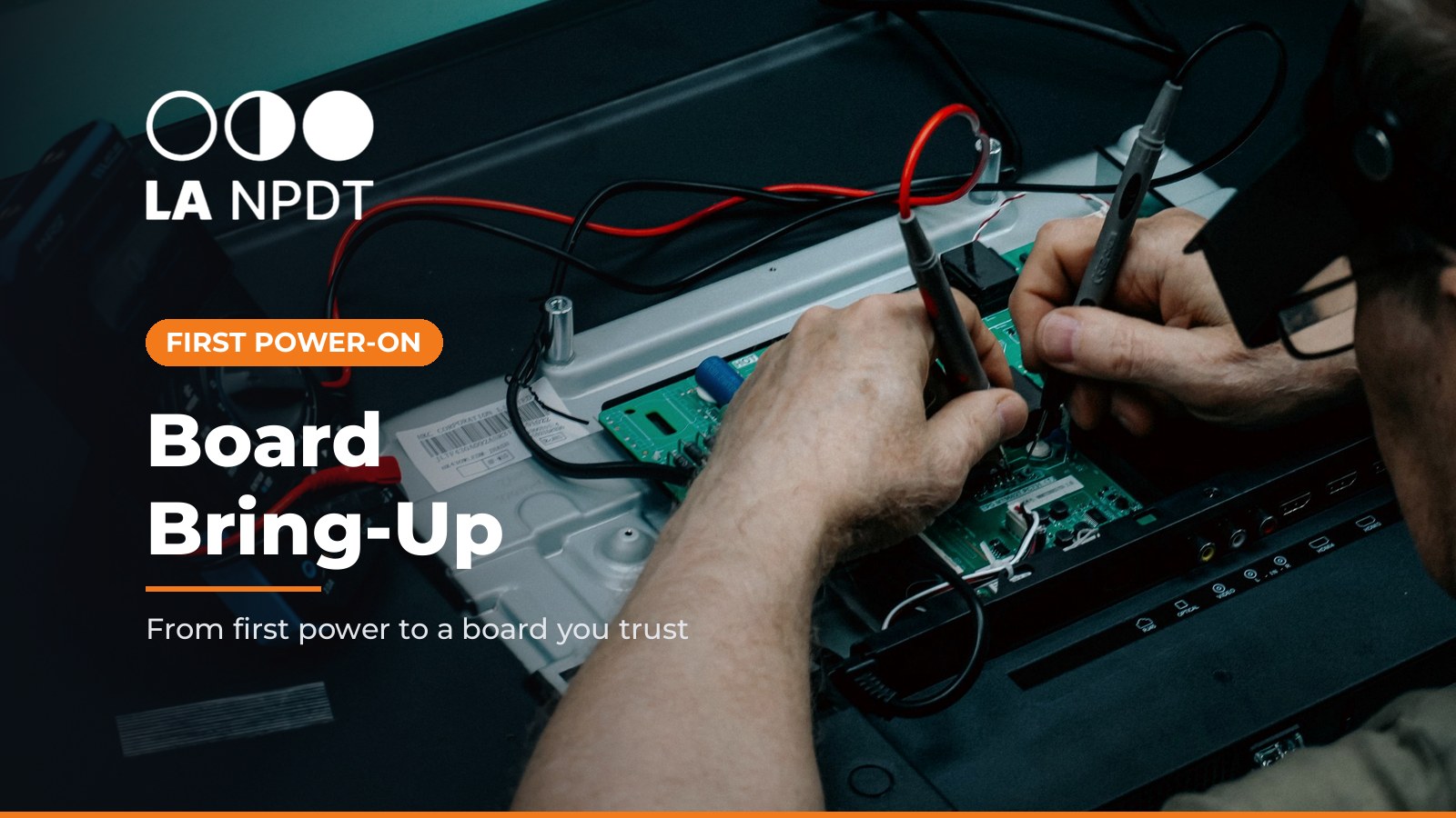
Board bring-up is the process of checking and validating a printed circuit board assembly for the first time. The goal is to confirm the board was manufactured and assembled correctly and that each subsection of the design works as intended.
That is how Circuit Cellar's Andrew Levido defines it, and he adds an important limit: bring-up is not the same as validating the whole product.
It is usually limited to the hardware, with just enough firmware to prove the processor, its peripherals, and the circuits attached to them behave as expected (Circuit Cellar).
Test-tool maker ASSET InterTech describes the same work as a phased, repeatable sequence: verify assembly, test power, clocks, and basic connectivity, debug the firmware and low-level software, then load the operating system or application software where there is one. That sequence repeats for every prototype run, and defects found along the way often turn into engineering change orders for the next spin (ASSET InterTech).
In founder terms: PCB bring-up is where the schematic and layout stop being a drawing and start being evidence.
Why bring-up matters before anything else depends on the board
Bring-up sits at a hinge in the program. The boards that pass it go into works-like prototypes, enclosure fit checks, user testing, and pre-compliance work. A board that only "mostly works" pushes risk into every one of those steps.
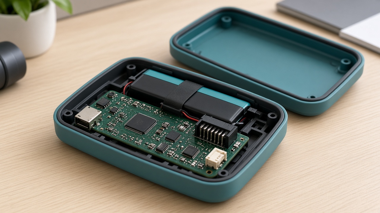
- Enclosure: the board outline, connector faces, battery, and keepouts drive the housing. If bring-up forces a connector move or a bigger regulator, the enclosure changes too. See enclosure design for electronics.
- Testing and beta: a beta built on unproven boards measures your rework, not your product. See stages of product testing and hardware beta testing.
- Certification: RF devices must be authorized under FCC rules before they are marketed or imported in the United States, and changes to an approved design may require additional approval (FCC Equipment Authorization). That is a strong reason to settle the radio, antenna, and power design during bring-up, not after the lab visit.
- Design freeze: you cannot honestly freeze electronics that have not passed bring-up on the current revision. See design freeze.
Before the boards arrive: plan bring-up during the PCB design review
The cheapest bring-up fixes happen in CAD. Use the PCB design review to ask, "How will we bring this board up?"
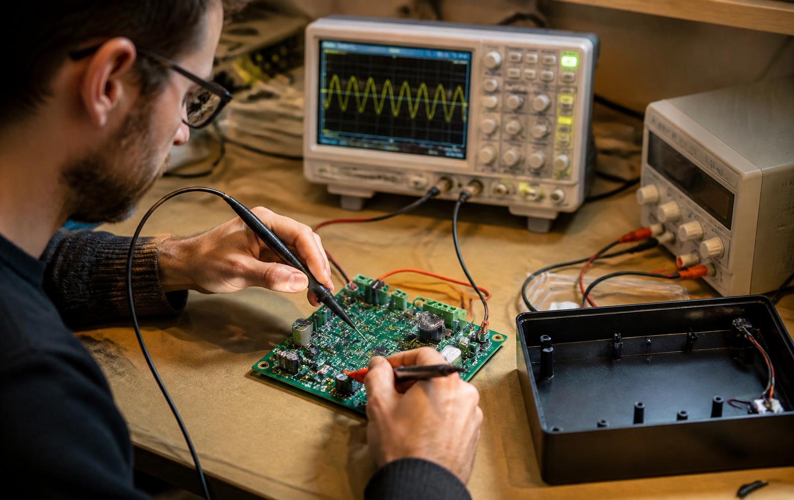
- Test points on every power rail, key clocks, reset, and critical signals, reachable with a probe once the board sits in a fixture or partial enclosure.
- A debug and programming header (SWD, JTAG, or the vendor's equivalent) plus a serial console. Bring-up without a debug path wastes days.
- Isolation options: zero-ohm links, jumpers, or solder bridges that let you power one rail or block at a time.
- Boundary-scan access on complex digital boards. IEEE 1149.1 defines boundary-scan test logic that helps test the interconnections between integrated circuits once they are assembled on a PCB (IEEE 1149.1). Whether it is worth it depends on the parts and pin density; decide during review, not on the bench.
- A written bring-up plan that lists the expected current at first power, the expected value of each rail, and the order you will test blocks. Circuit Cellar recommends a written plan or checklist for every bring-up so the process is repeatable across prototype rounds (Circuit Cellar).
- A real BOM that matches what was placed, including any substitutions the assembler made. For layout-to-fabrication handoff, see PCB design for manufacturing.
Board bring-up checklist, step by step
Use this board bring-up checklist on every board in the first lot. Work one board at a time until the first one passes, then repeat the same steps on the rest.
1. Label every board and open a log
Give each board a unique ID before power touches it, and keep a per-board log of tests, results, and rework. When several boards are in different states of rework, the log is the only thing that keeps them straight (Circuit Cellar).
2. Inspect before you power
Look for wrong or rotated parts, polarity on diodes, electrolytics, and tantalums, solder bridges, dry joints, and damage. Check suspicious areas for shorts and continuity. Fix what you find now, not after something gets hot.
3. Run unpowered checks
Measure resistance from each rail to ground. A rail that reads as a dead short is a stop sign. Compare against a known-good board once you have one.
4. First power with a current-limited supply
Apply power from a bench supply with the current limit set low, and watch the current draw against the value in your plan. Check every rail is within specification. A thermal camera, if you have one, quickly shows parts heating more than expected (Circuit Cellar).
5. Confirm clocks and reset
Probe the main oscillator or crystal and check reset and power-good behavior with an oscilloscope. A processor that never leaves reset can look like a "dead" chip.
6. Load a minimal firmware image
Flash something tiny: boot, toggle a GPIO or blink an LED. That proves the processor boots, can be programmed, and runs at the expected clock. Then bring up a debug output such as a UART or USB console so the board can tell you what it is doing (Circuit Cellar).
7. Bring up one block at a time
Exercise each peripheral and circuit block in turn: sensors, memory, displays, motor drivers, charging, radios, analog front ends. Isolate blocks where you can, and write only enough code to prove the hardware. Where a peripheral needs heavy configuration, write that code so it can be reused in the real driver.
8. Rework carefully and document every change
Cut traces, swap values, or add bodge wires as needed, and make them mechanically robust if the board will live on the bench for weeks. Then record every change on the schematic or in the log so it reaches the other prototypes and the next revision (Circuit Cellar).
9. Handle boards as ESD-sensitive
Use grounded mats and wrist straps. The EOS/ESD Association notes that electrostatic discharge can destroy a device outright or leave a latent defect that escapes immediate detection and causes premature failure later (ESDA). A board damaged on your bench can send you chasing a design bug that is not there.
10. Close out the board
Mark each board pass, pass with rework, or fail, and list open issues with an owner. Only passing boards go into integrated prototypes, enclosures, or user tests.
Hardware bring-up vs firmware bring-up vs validation
Teams use these words loosely. Keeping them apart avoids false "done" claims.
Hardware bring-up | Firmware bring-up | Design validation | |
|---|---|---|---|
Main question | Was the board built right, and does each circuit work? | Do the drivers, boot, and low-level software run reliably on this hardware? | Does the product meet user needs and requirements in real use? |
Typical evidence | Rail measurements, current draw, clock and reset traces, block-level tests, rework log | Boot logs, driver tests, programming and update tests | Test reports against requirements, field or beta results |
Who leads | Electronics engineer | Firmware engineer, with electronics support | Product team, test, and users |
Firmware needed | Minimal, only to exercise hardware | Most of the low-level stack | Release-candidate firmware |
Circuit Cellar draws the first line clearly: bring-up validates the hardware, not the whole system (Circuit Cellar). For the full test progression, see design verification and validation. If you are using AI coding assistants for early drivers, treat their output as a draft until it is tested on real hardware; see AI tools for hardware prototyping.
Common PCB bring-up problems and where to look first
These are common patterns, not a diagnosis. Your schematic and measurements decide.
What you see | Where to look first |
|---|---|
Current limit trips at first power | Shorts, reversed polarity parts, wrong regulator, solder bridges near power pins |
A rail is present but out of spec | Feedback resistor values, regulator part number, load on that rail |
Processor will not program | Debug header pinout, reset line, boot-mode pins, programmer target voltage |
Firmware runs but timing is wrong | Clock source, crystal load capacitors, clock configuration in firmware |
A peripheral does not respond | Bus pull-ups, addresses, chip selects, footprint orientation, power to that block |
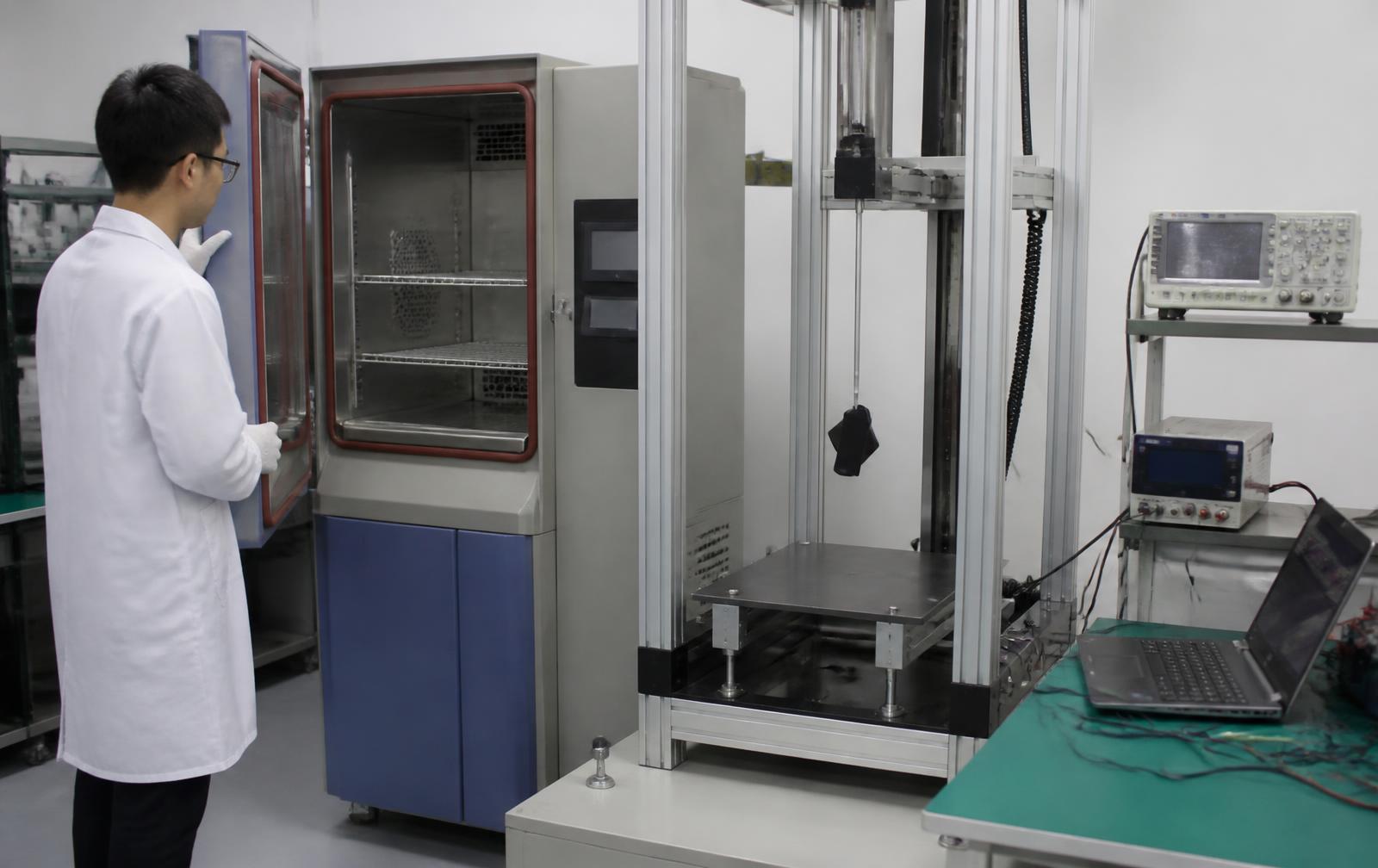
Board works on the bench, fails in the housing | Thermal, cable strain, connector access, RF near metal or batteries |
After bring-up: turn findings into the next spin
Bring-up ends with a list, and that list is the most valuable output:
- Rework log to design change. Every bodge becomes a schematic or layout change on the next revision, reviewed like any other engineering change. See the engineering change order process.
- Expect more than one spin. ASSET InterTech notes that complex systems rarely go straight to volume production after the first prototype run, and issues found in testing drive changes for the next one (ASSET InterTech). Budget the schedule for it.
- Update the BOM and the assembly notes so the assembler builds the next lot the way the working board actually is. For the build side, see the PCB assembly process from EVT boards to production.
- Feed the enclosure and test plans with the real board outline, connector positions, and thermal behavior.
- Inspect the next lot properly. A first article inspection catches build drift before bring-up starts again.
For where bring-up sits in the bigger picture, see electronic product prototyping: from dev board to custom PCB and electronic product development stages.
How LA NPDT approaches bring-up
LA NPDT does design, engineering, and prototyping in-house at our facility in Ruston, Louisiana. Parts and components may be sourced globally; the development work stays under one roof. For electronics programs that means schematic, PCB layout, firmware, and bring-up happen next to the mechanical prototypes and enclosures the boards go into, so a bring-up finding can reach CAD the same day.
In practice:
- Bring-up planning starts at the PCB design review (test points, debug access, isolation)
- A written bring-up plan and per-board log for each prototype lot
- Firmware written to prove the hardware first, then grown into the product stack
- Findings rolled into the next revision with a clear change record
If you have boards on the bench, or a schematic that is about to go to layout, and want an engineer's view on bring-up readiness, see our electronic product design services or book a free initial consultation. Phone: +1 318-200-0526.
Boards on the bench and not sure they are ready?
Talk with an engineer about bring-up planning, PCB fixes, and the next board spin. Phone: +1 318-200-0526.
Sources
Frequently asked questions
What is board bring-up?
Board bring-up is the first power-on and step-by-step validation of a new printed circuit board assembly. It confirms the board was built correctly and that each circuit block works, using only as much firmware as needed to exercise the hardware.
What should a board bring-up checklist include?
Board labeling and a log, visual inspection, unpowered rail-to-ground checks, current-limited first power with rail measurements, clock and reset checks, a minimal firmware image with a debug console, block-by-block tests, ESD-safe handling, and documented rework.
What is the difference between hardware bring-up and firmware bring-up?
Hardware bring-up proves the board was built right and each circuit works. Firmware bring-up proves the boot process, drivers, and low-level software run reliably on that hardware. Hardware bring-up usually comes first and uses only minimal firmware.
What equipment do you need for PCB bring-up?
At minimum, a current-limited bench power supply, a multimeter, an oscilloscope, a debug probe or programmer for the processor, and ESD protection such as a grounded mat and wrist strap. A thermal camera helps spot parts that run hotter than expected.
How long does board bring-up take?
It depends on board complexity, the number of circuit blocks, and how many problems turn up. Plan for bring-up on every prototype run, and plan for more than one board spin, because findings from each round feed design changes for the next.
Should you design the enclosure before bring-up is finished?
Start the enclosure in parallel around the board outline and connector positions, but do not freeze or tool it until bring-up on the current board revision is complete. Bring-up findings can move connectors, change parts, or reveal thermal issues that affect the housing.
Services related to this guide
- Product design servicesIndustrial design and CAD taken all the way to manufacturable files.
- Rapid prototypingWorking prototypes in days, from 3D printing to vacuum casting.
- Electronic design servicesSchematic, PCB layout, firmware and bring-up, through to production handoff.
- Product development examplesReal projects we designed, prototyped and shipped.